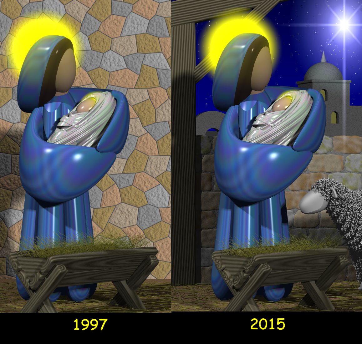
Every year since 1995 I’ve created my own computer rendered Christmas cards using the Persistence of Vision Ray Tracer also known as POV-Ray. Each year it’s been a challenge to come up with something new and different. Last year finding myself totally clueless as to what to do, I decided to recycle and update the previous year’s card. Last year’s card was a revised version of my 1997 Mary and Child card which was probably my favorite and the favorite of many friends and family. Note you can click on any of the images in this blog to see larger versions.
With the exception of 2013 in which I used a background photograph to complete the image, all of my cards have been 100% CGI rendered using POV-Ray. As it turned out the use of that photograph led to a lawsuit which is a whole other story. I’m pleased to report lawsuit was successfully settled out of court and I will chronicle that particular story elsewhere at a later time.
Step into the Real World
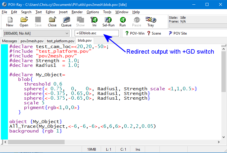
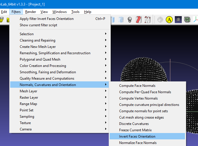
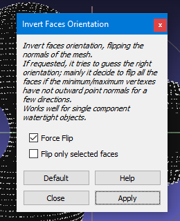
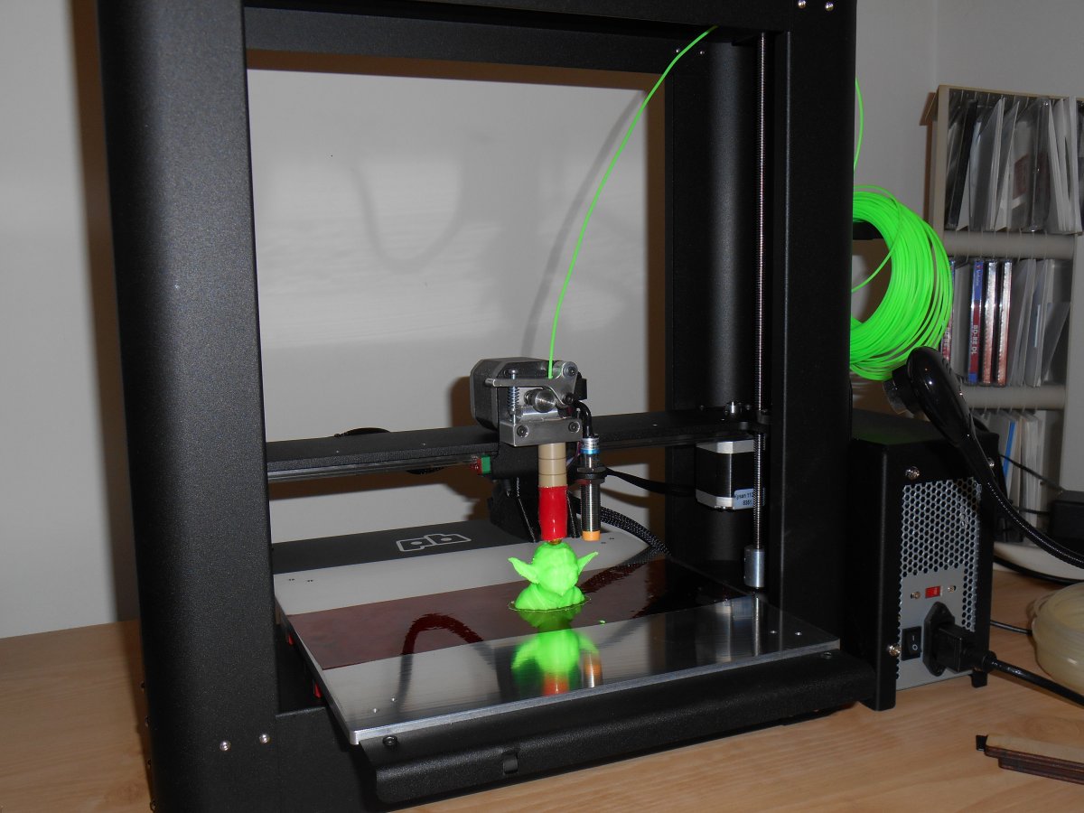 Because the figures and objects in my Christmas cards have all been rendered objects. They’ve never before existed in the real world. I’ve always wondered what some of these figures would look like if they could step from the virtual world of CGI into the material world. A year and a half ago as a 60th birthday present to myself I purchased a Printrbot Metal Plus 3D printer. One of the first things I tried to do with it was to print one of the figures from my Christmas cards. Specifically I wanted to create the Archangel Gabriel which is loosely modeled after the logo for my church St. Gabriel the Archangel Catholic Church in Indianapolis. Unfortunately POV-Ray will not export its files in a format capable of being used by 3D printer. The project went on the back shelf for quite some time until earlier this year I dove headlong into the issue of converting POV-Ray files into something 3D printable. I was able to come up with a technique that works and I’ve already described that in these articles.
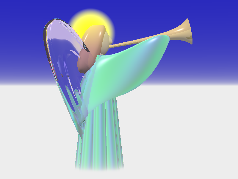
When it came time to do the 2016 card, obviously I was going to have to recycle one of my old designs like I did in 2015 but I decided to do something different. If we were going to reimagine an earlier card let’s go back to the beginning with that first 1995 card shown here.

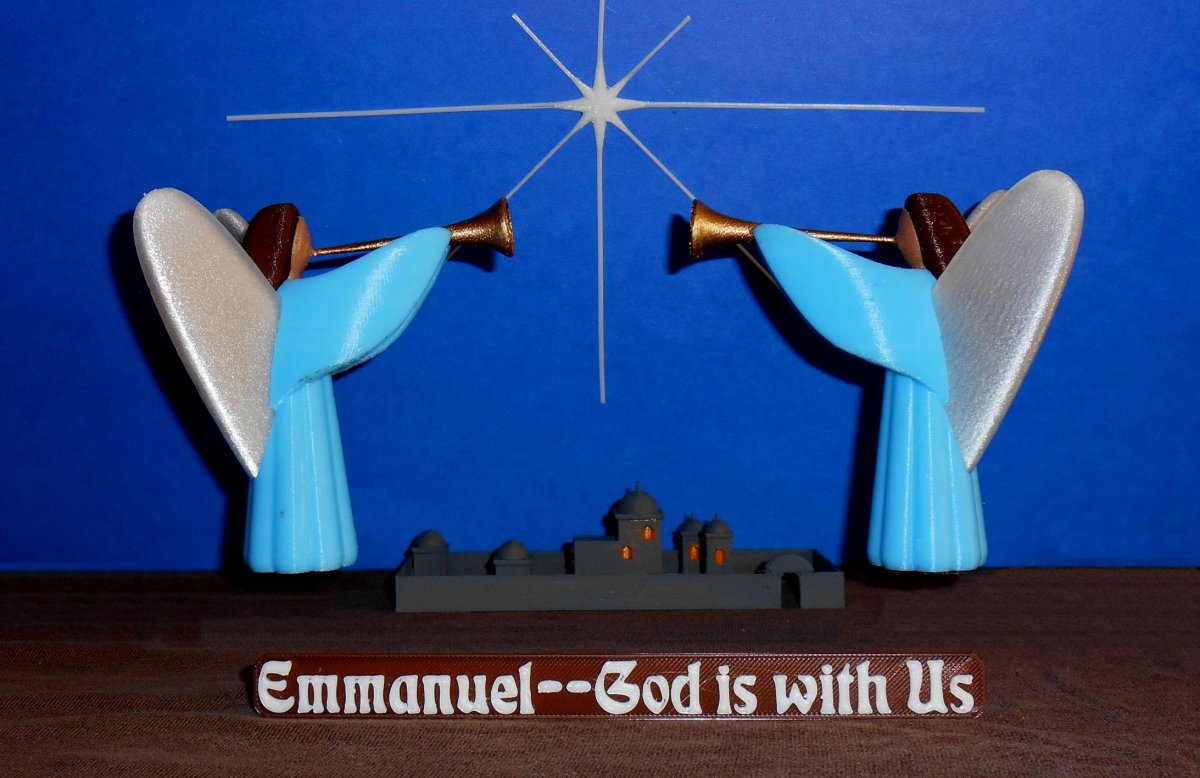
This image has two of the St. Gabriel angels, the star of Bethlehem, and the little town of Bethlehem itself in the distance. I previously chronicled how I design and rendered the St. Gabriel angels as seen here.
And how I did the 1995 card as seen here.
What if I took a couple of my 3D printed angels which had finally come to life and photographed them in a real world re-creation of that very first CGI card? I wasn’t sure I would be able to pull it off and I held out the possibility that I might have to scrap the idea altogether and do something traditionally CGI. But I forged ahead and attempt to re-create a physical version of that 1995 card.
Printing the Parts
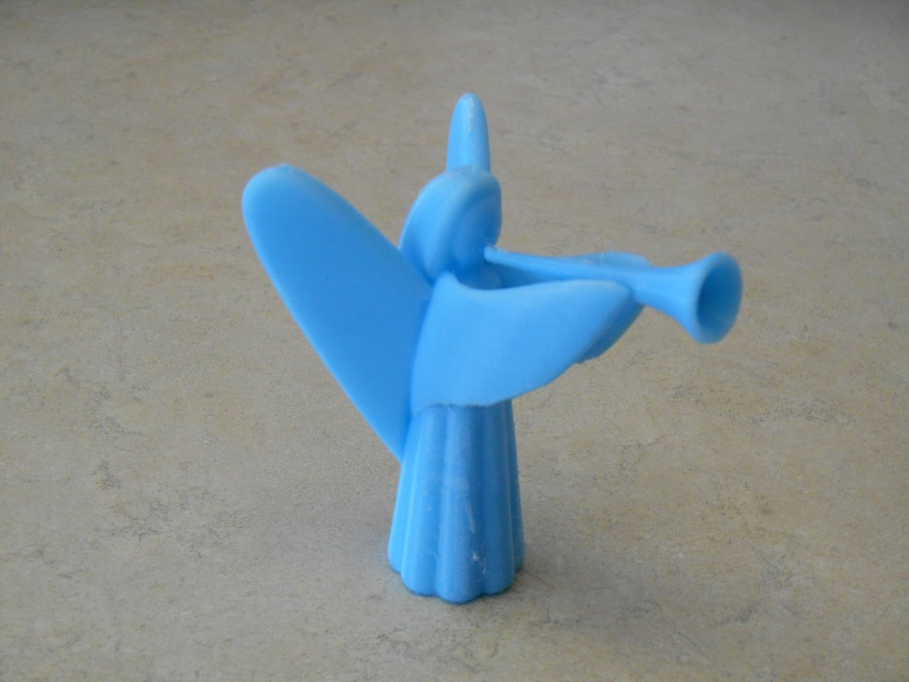
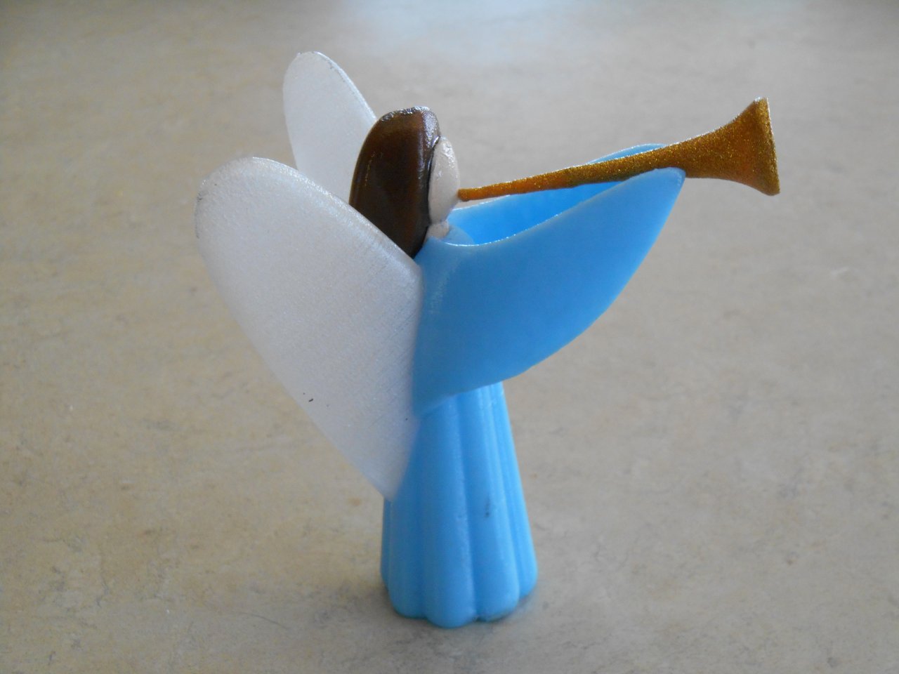
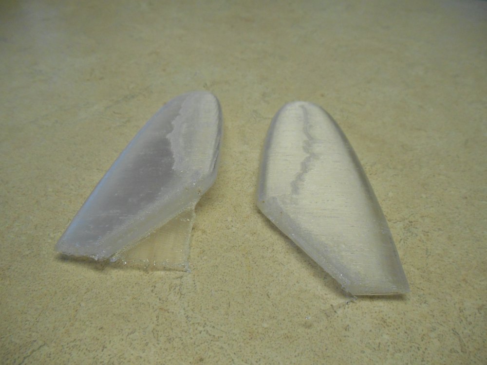
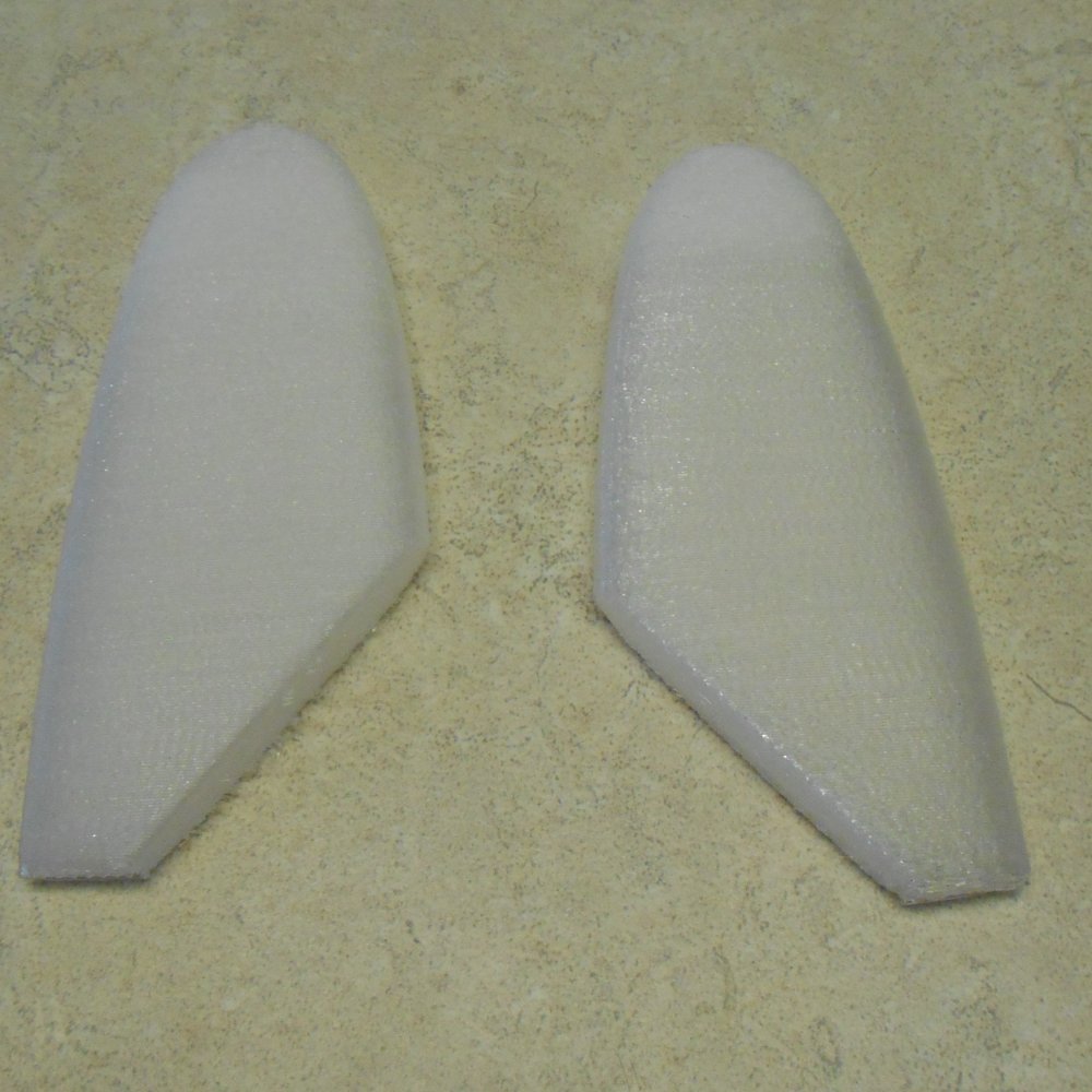
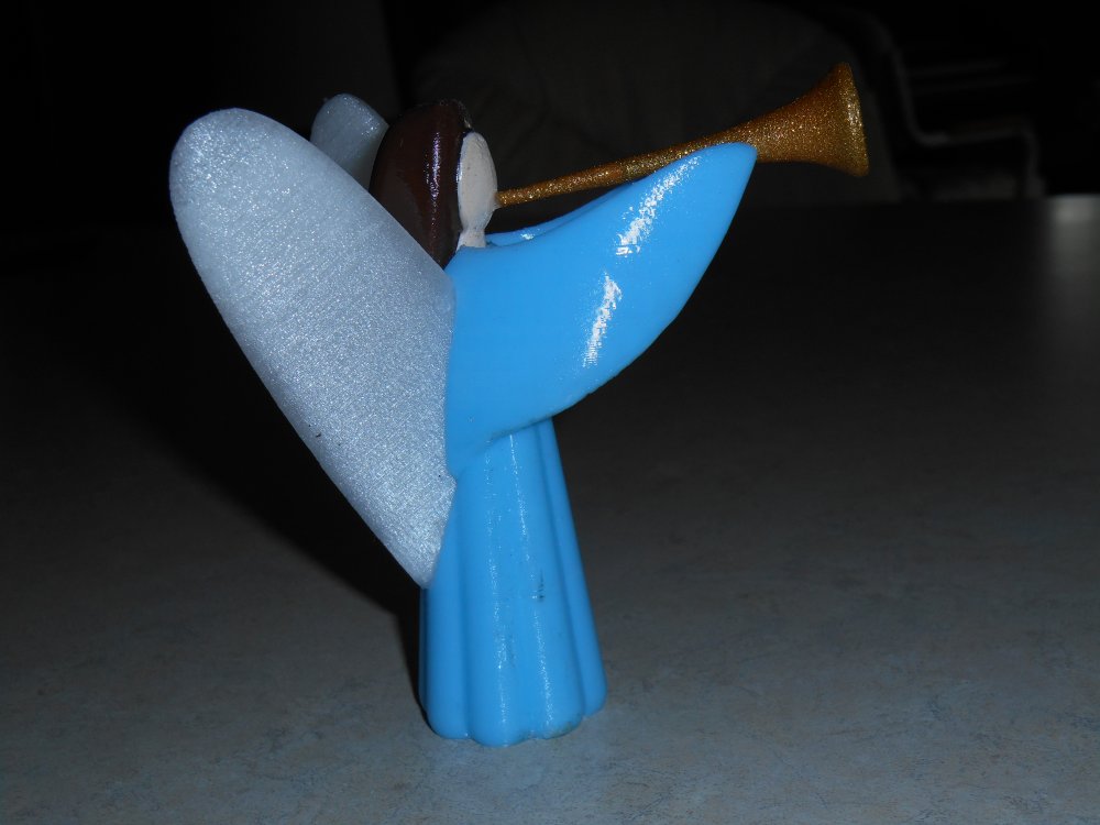
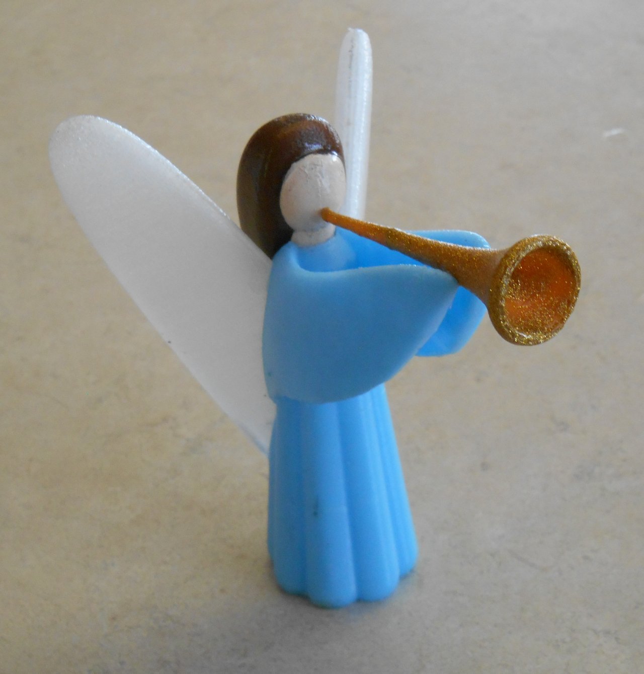 I had already successfully 3D printed an angel but while gluing together the face and head of the model we got them at slightly the wrong angle. I also wasn’t satisfied with the paint that we used for the skin tone of the face and for the gold color on the trumpet. I made the decision to 3D print 2 more complete Angel models. It took just over six hours each to print the two angels. The wings, body, hair, face, and trumpet are all printed as separate pieces and then glued together.
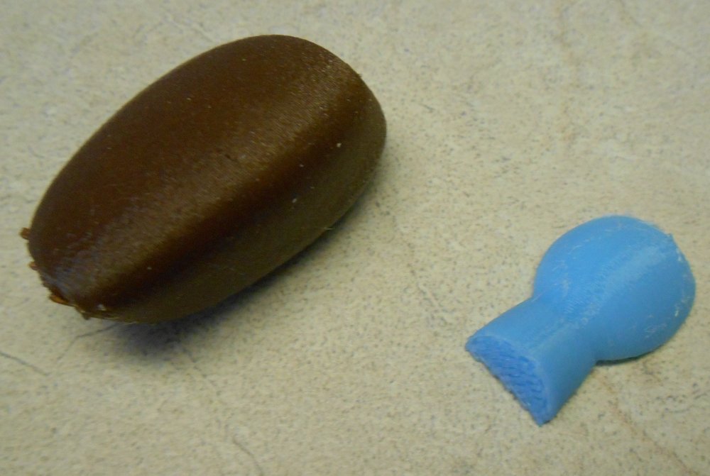
I should note that the halo on the angel in the CGI version is really just a glowing ball of gas. I did some experimentation with how to make physical representation of that halo but it just look like a big yellow Green Bay Packers football helmet no matter what I did. I made this sort of executive decision to just ignore the halo.
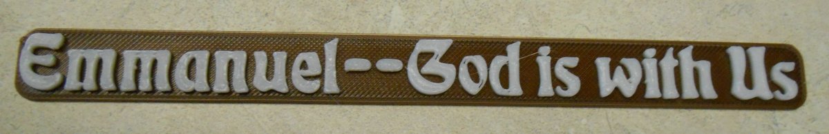
Apart from the angels there are three other objects in the original image. We have the little town of Bethlehem, the star, and the text message “Emmanuel — God with Us”. I also needed to somehow come up with a physical representation from the desert floor and the sky in the background.
After printing two brand-new copies of the angels, I next tackled the town because it was relatively straightforward. It consisted of nothing but boxes and spheres arranged to look like buildings inside a walled city. There is an arched doorway to one side through which you can see a courtyard. I simply re-created these objects using Blender 3D CAD software rather than try to export from POV-Ray. The rendered version uses a dark gray texture with a yellow indent inserted into the windows of the buildings to make them look like there were lights inside. I didn’t have any yellow plastic but I did have orange so I decided to print the town in orange and then paint it dark gray hoping to leave the windows unpainted with the orange plastic shining through. If I didn’t like the looks of that or was unable to keep the gray paint out of the indents for the windows, I had also purchased some yellow paint that I thought we could dab inside the windows with a toothpick. Below are some images of the unpainted and painted versions. I decided to stick with the orange windows.

I had to decide what to do about the text. I could just take the photograph of the angels and the city and then use photo editing to superimpose the text over it. But that seems like cheating if I was trying to re-create the image in the physical world. I tried 3D printing the text directly onto the build plate with some thin strands of plastic connecting the letters. But when you are printing very small parts such as those individual letters, it’s hard to get good adhesion to the build plate and you end up with globs of gooey plastic balling up around the nozzle. I decided I had to print a background plate with the letters on top of it.
Because I do not have a dual extrusion printer I had to set it up so that it printed the plate in a dark brown plastic, then paused while I changed the filament, and then continued to print the letters in a different color in this case white. Unfortunately the Printrbot Metal Plus does not have an LCD control panel or any kind of physical controls. Therefore the typical methods of pausing and resuming a print in the middle don’t work. I will do a completely separate blog post from a technical standpoint on how I managed to get the pause and resume to work. Here’s a photo of the text plate that we printed.
The most difficult part of this project was trying to print the star of Bethlehem. Again I could have copped out and superimposed the star using photo editing software but I really wanted to make a physical 3D printed representation of the star with the rays of light radiating from it as it did in the original image. Again the problem is it’s very difficult to get very thin pieces of plastic to adhere to the build plate. Although I’ve had my printer a year and a half I still wasn’t satisfied with my techniques for getting parts to stick. My method of choice was to put Elmer’s glue stick on top of the Kapton tape that is on the build plate. I used 70° C heat on the plate.
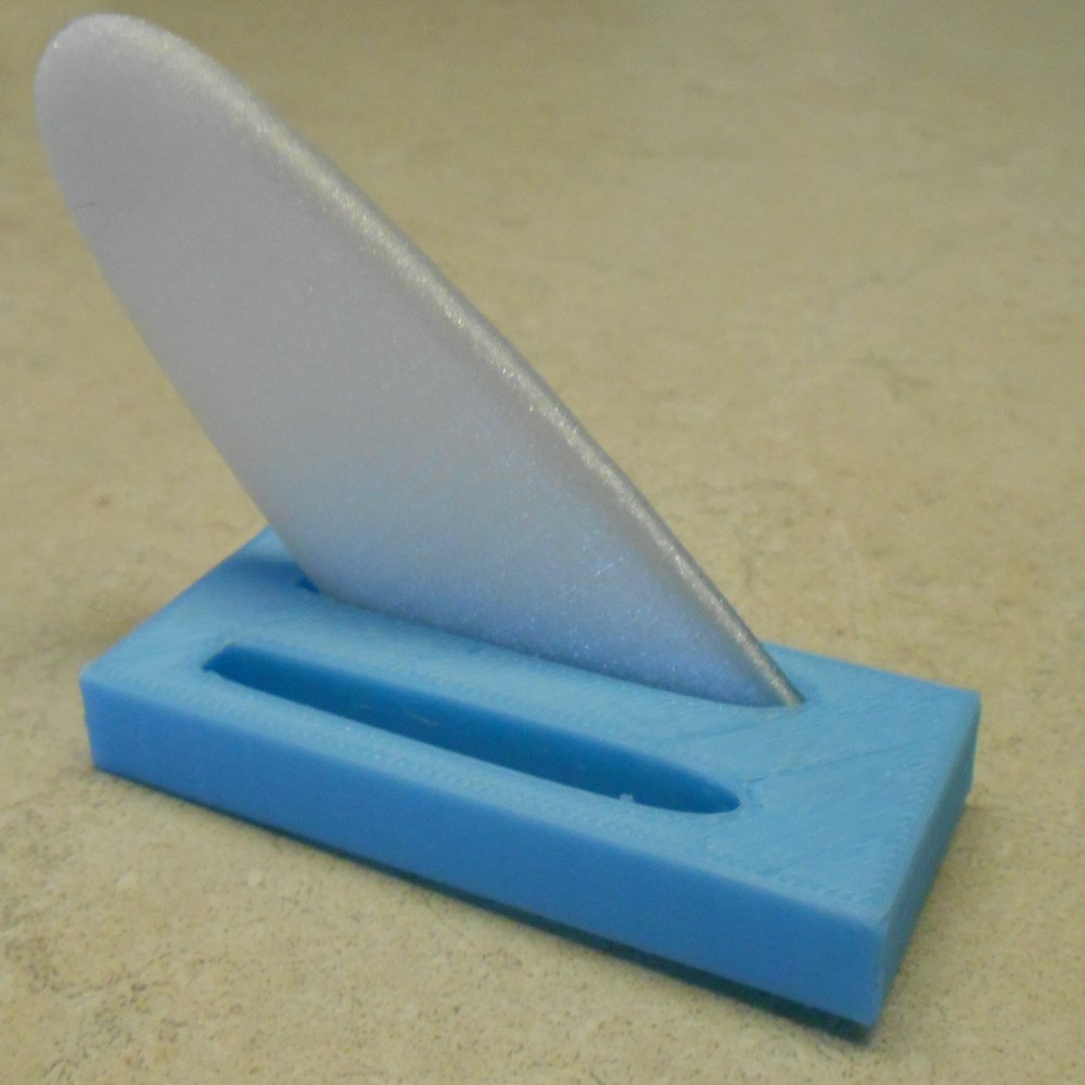
We must’ve tried 10 different times to print the star and it just wasn’t going to work. Finally I came up with the idea of printing the star without the rays and then printing some strips of plastic that we would use as rays that we would glue down in a radiating pattern around the original star. In order to get the strips to print, I anchored them at each end. Here’s what that looked like.

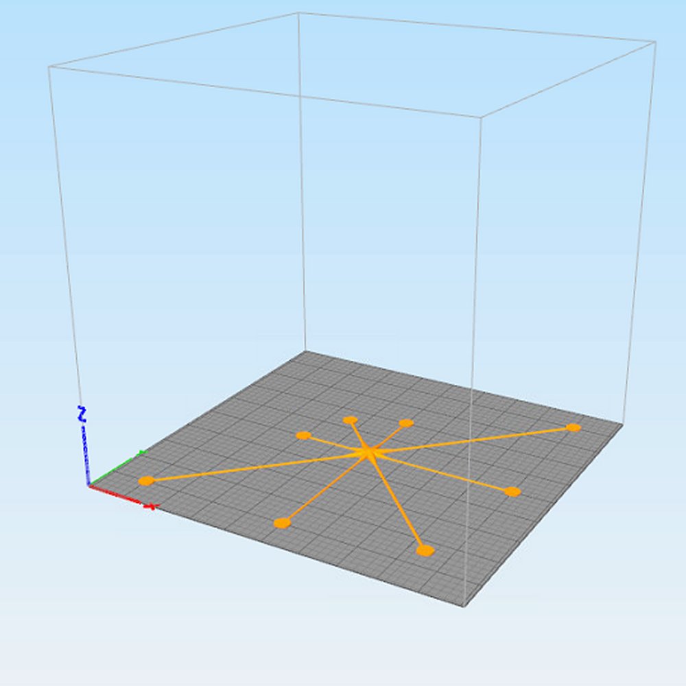 After I had this contingency available, I decided to go back to my original plan to print the rays and the star in one unit. However this time I decided to put a small disc at the end of each ray to anchor it to the build plate in the same way that that bar across the printed rays helped them print. It still took two or three attempts because we didn’t get the glue spread all the way into the corners at the exact proper place but eventually we did get the entire star with the rays printed as a single unit filling almost the entire 10 x 10″ build plate. Shown in this image on the right we had to put it on a diagonal because that longest ray is more than the 10 inch width of the plate. We later cut the discs off the tips of the rays. Here’s the results.

Building a Background
Finally I had to figure out what to do for the sky background and the desert floor. The original images depicted the sky using a gradient color of dark blue to black with a sprinkling of small stars randomly scattered throughout. I considered the possibility of printing out a star pattern and taping it to a piece of cardboard for a backdrop. However my dad found an old piece of dark blue poster board that looked pretty good so I decided to use it and forgo any other stars other than the Bethlehem star. We used glue stick to stick the star to the poster board. We had to reposition it several times and sometimes the rays tended to droop a little but I didn’t care. It looked pretty good. We taped the poster board to the lid of a cardboard box and fastened it to the table using a C clamp.
Speaking of the table, I was going to set it up on my dining room table and use the oak wood grain as a dark brown surface to represent the ground. I also tried some brown placemats that normally sit on my dining room table but none of these surfaces appealed to me in test photographs. Because I wanted to be able to visualize the camera angles and adjust the lighting, I decided to set up the scene on a hospital bed table that I have. I used to use it in my bedroom when I needed my laptop in front of me on my bed. These days my laptop is connected into my bedroom TV and I’ve not used the tray table in a long time. It was a good choice because it was big enough, it had a brown surface, and the height was adjustable which let me eyeball the camera angles. We could also roll it around the dining room so that the ceiling lights and other room lights as well as light coming in the windows would hit the scene at various angles.
In the end, the fake wood texture on the table didn’t look right for the floor either. I needed some brown cloth and it turns out I have an ordinary brown cotton T-shirt that was just right. We slipped it over the end of the table and set all of the pieces on top of it. Here is a photo that shows my set up with my digital camera sitting on a tiny tabletop tripod.

Note that in the original image the angels are hovering over the city. I needed to make some little 3D printed stands to hold them up in the air. I would later Photoshop them to remove them from the scene. Also the T-shirt and poster board were not quite wide enough in certain areas to fill the scene so I used a little retouching to paint out some background. I tried to keep the digital manipulations to a minimum but there’s no way I could get around this without building a really complicated suspension system to hold the angels up in the air. It just wasn’t worth it.
Lighting Issues
I tried a variety of lighting scenarios. I like the way the figures look under flash photography. The highlights look really good and it makes the figures stand out against the background. The problem is that the figures then cast a shadow on the dark blue poster board which of course is unrealistic. This image is a flash photograph that shows the shadow problem and points out other areas digitally retouched.

Below is another image that attempts to eliminate the shadow problems by using an overhead light from the dining room chandelier. I also increased the distance from the angels to the poster board. However that created a scale issue for the size of the Bethlehem star. Also because the poster board has a slick surface I get a little bit of specular highlight from any kind of lighting depending on the angle.

I tried a variety of other room lighting including from my kitchen bar and natural light coming through the dining room windows. I tried using Photoshop to get rid of the shadows on the poster board. I tried evening out the background to get rid of the specular highlight by picking a color and doing a flood fill. None of the retouching looked right.
In the end I just decided that what I was creating was not really a photorealistic image depicting angels over the city of Bethlehem. What I was depicting was a photograph of a diorama of little plastic statues sitting in front of a cardboard background. I moved the angels very close to the poster board which minimized the shadows but does not eliminate them. I did minimal retouching to extend the floor as needed. I retouched to eliminate the angels supports. The final image is a flash photo. I adjusted the contrast to brighten the objects and darken the background.
The Final Image
Here is the final image as I sent it VistaPrint.com to be printed. The printed cards arrived the last week of November and I began working on the interior message which I would customize using my laser printer. Unfortunately life got in the way. On December 3 I had to be rushed to the hospital in respiratory distress. As of this writing on Christmas day I’m still the hospital and will not return home until sometime the middle of next week. At that point I plan to pick up the task of customizing the interior of the Christmas cards and mailing them to friends and family even though they won’t arrive until early January.
Here’s a comparison of that image side-by-side with the original 1995 rendering. Note that the aspect ratio is different because of the way they were ultimately printed. The original 1995 image was printed on one fourth of 8.5 x 11″ sheet of paper. The new image was created according to Vista Print landscape format folding holiday card specifications that comes out about 5 x 7″.
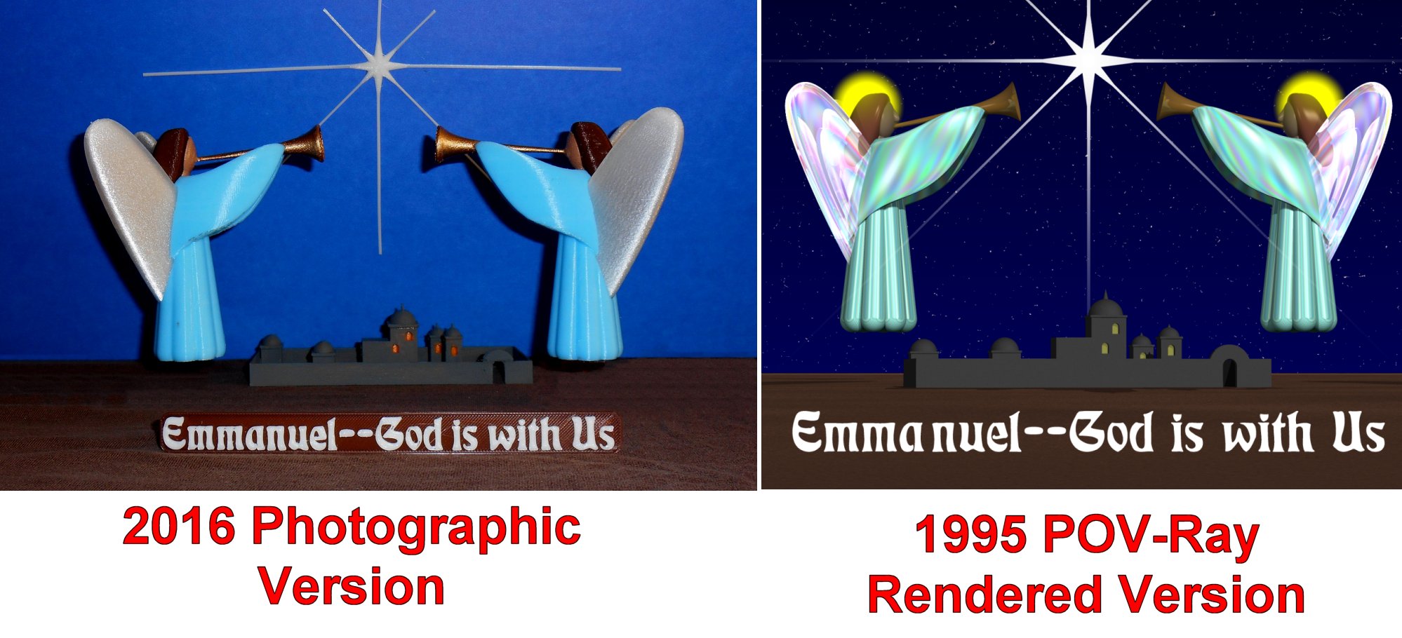
Overall it was a fun experiment in trying to drag the virtual world into the material world. I doubt that I will do it again for the Christmas card but I would like to see 3D printed versions of some of my other figures especially the 1997 Mary and Child. Who knows… Maybe someday I will 3D print an entire nativity scene.