My Fascination with Graphics

Featured

When I first got involved with computers, one of the things that most intrigued me was the use of computers to generate art. Having very little physical ability and eventually losing the use of my hands completely, traditional artistic media were beyond my grasp. But like many aspects of my life, technology comes to the rescue and allows me to do things that would not otherwise be able to do. Computer graphics gives me the opportunity to express myself artistically despite my severe disability.

In the late 1980s I got involved with an online project called the Persistence of Vision Ray Tracer or POV-Ray for short. I began contributing code to this open-source freeware program that allows you to create photorealistic images using nothing but a text language and a lot of computing power. Eventually I became the team manager for the POV-Team and even published two editions of the book entitled “Ray-Tracing Creations” which sold several thousand copies but is long out of print.

In 1995 I created my first Christmas card using my ray-traced computer-generated artwork. I’ve created a new image every year since then as well as used ray tracing for other graphics projects. In this blog I plan to share my images as well as explanations of how my artwork is created. Some of it will be articles about how they were created and others will be video demonstrations.

How I Created My 2018 Christmas Card

The image above is my 2018 Christmas card. It was created using the Persistence on Vision Ray Tracer also known as POV-Ray. I’ve created a Christmas card every year since 1995 using the software.

This year’s image is a little bit simpler than most. I’ve sort of run out of ideas. You can see a gallery of all my Christmas card images on my Facebook page at this link.

Here is a YouTube video explaining a little bit about the history of the card and other images which inspired it.

Years ago there was a program called “SUDS” that was supposed to create spheres that touched one another like bubbles in soapsuds. It was used to create some other classic POV-Ray images. I couldn’t find a copy of the program but POV-Team leader Chris Cason was able to locate an old copy. Unfortunately it was compiled for 16-bit Windows and would not run on a modern 64-bit Windows system. It did include the source code and I tried to translate the code into the POV scene description language. But I never did get decent results. I think it was designed to create spheres of widely different diameters large and small so that the small ones would fill in the gaps. I wanted something where the variability of the diameters was not so significant.

In the end, I just created my own algorithm for randomly placing the spheres. It would pick a random X/Y coordinate and then dropped the ball down on the Z-axis until it hit the bottom or it touched another sphere. My intent was to continue the process so that once it touched it would then rotate downward until it made contact with at least one or two other spheres but that was going to be too complicated and I never did implement it.

When you randomly place objects, you can still have large gaps so I had to put way more spheres than would normally be necessary to fill the image. I just kept adding more and more spheres until I had filled almost all the gaps. Residency in the video I cropped the image so that many of the spheres are outside the actual visible area and many others are hidden behind the top layers.

I then manually placed the 14 spheres spelling out the words “Merry Christmas”. Each of the 14 spheres has an image map of the letter embossed on to it.

Although it looks likely Merry Christmas ornaments are approximately the same level, if you watch the YouTube video which rotates the scene at a different angle, you can see that those lettered ornaments are actually as one quite different heights. Only when you rotate the into the right perspective doesn’t make the words visible.

Some point I will go back and rewrite the algorithm so that the spheres drop down into place properly and fill in the gaps more realistically but for purposes of this image it was good enough as well as viewed from a straight on perspective.

Here is what the interior of the card looks like.


My 2017 Christmas Card: Santa Adopts New Technology

Every year since 1995 I created my own custom designed Christmas cards. All but one of them have used computer graphics rendering using the Persistence of Vision Ray Tracer (POV-Ray). Last year I did a photograph of some 3D printed figures that re-created the scene from my 1995 card. In recent years because I’ve run out of ideas, I’ve sort of recycled previous years cards with updates and tweaks. It’s been since 2014 that I created an original card.

For 2017 I finally came up with an idea for new card. Inspired by my fascination for 3D printing I began to wonder what would happen if Santa Claus adopted this new technology for creating toys. Here is the image that resulted from that concept. Note you can click on any of the images in this blog to see a larger version.

I thought I would describe how I created the image and point out some of the little references that inspired the card.

First of all, this 3D printer is loosely inspired by a printer called the Creality CR-10. It is a very popular relatively new printer with a large build area and can be purchased for under $400 for the standard model and under $500 for the larger version. Here are a couple of views of this printer followed by a close-up of my model.


The color trim stripes on these printers are usually either a light blue or yellow/beige color but I decided to give these in more Christmas feel by making them either red or green. When creating such images, you have to decide how much detail you want to create in the model. In the finally mage, even the largest printer in the foreground is only going to be a couple of inches square on the final Christmas card so you don’t really need to put in a lot of detail. For example from some angles that you look at the printer, you don’t see the extruder motor that is on the left side of the cross beam because it is mostly hidden by the upright. So I didn’t bother to model the extruder motor.

The image below is a close-up view of the backside which you never see, none of the threaded rods that elevate the crossbeam and extruder are there. As mentioned before the extruder motor is missing. The piece of plastic filament that runs from the spool to where the extruder motor should be just stops in midair. The Bowden tube that feeds the filament into the nozzle similarly hangs in midair above where the motor should be. In fact there is no extruder nozzle because from the front view it would be hidden by the cooling fan. So I didn’t even bother to model any of the details. If I was ever going to reuse this model for a different scene that would view the printers from different angles then I would have bothered to create the details.

The filament running from the spool to where the extruder motor should be, the Bowden tube, and the cables running to the nozzle and fan were all modeled using Bezier splines. I did that so that I could move the nozzle left or right in the X direction or move the crossbeam up and down in the Z direction on different printers and the filament pieces and cables would continue to lineup properly. That is because the endpoints were attached to the objects. Had I wanted to, I could create an animation moving the nozzle up and down and left and right and all of the filament pieces and cables would have flexed properly.

Sometimes I gave into my urge to go ahead and model some details that may or may not show up in the final image.

In this close-up you can see that there is an image map in the display window with text telling how much print time is remaining on the current print. Had I been a real fanatic I would have created different image maps for each of the printers because they would naturally have different amounts of time remaining. But I was sure we would not be able to read the text anyway so they all read the same amount. One detail where I put a lot of effort was modeling the little document clips that hold the removable print bed in place. It turns out that in the full image these little clips really stand out and people who are familiar with this technique for securing 3D printer beds will instantly recognize this detail.

Another bit of poetic license that I took in the design of the printer was that the power supply, display, and spool holder are not black like they are in the actual printer. I was concerned that with a dark printer and a lot of clutter in the image, this little box would not show up. So I took the liberty to make it a sort of beige that was supposed to be reminiscent of an old school IBM PC computer case.

The next job was designing some toys to be printed. The most visible toy is a little robot being printed on the printer in the foreground. It is inspired by “Adabot” — the mascot of Adafruit Industries where I buy all of my electronic parts and maker supplies.

I wanted to have 2 different versions of each toy. One would be a completed version that would sit on the shelf next to the printer and the other would be the parts of the toy as they would sit on the printer platform. A shape like the robot cannot be printed all at once. You could print the body and head together although they would likely be separate. But you would definitely print the knobs and legs separately. Here is a close-up.

I didn’t put a lot of detail into the robot and he is not an exact duplicate of Adabot but people who are familiar with the character will immediately recognize him. In addition to using the robot as one of the toys, I also wanted to depict a robot being printed on the computer tablet that is being held by the elf in the foreground of the picture. Here is the image map I used on that tablet.

The image above is a screen grab from Simplify 3D which is the program I use to actually 3D print objects. Unfortunately POV-Ray doesn’t export objects in a format that can be 3D printed or can be loaded by Simplify 3D. So I had to use CAD software Blender 3D to create another version of the robot just so that I could load it into Simplify 3D and create that screen grab. It only took me about a half-hour to re-create the robot using a different program because I had all of the dimensions and proportions already figured out in POV-Ray. It was pretty easy to model, export as a STL file, load it into Simplify and do the screen grab. I probably had way too much detail because you can barely see the robot on the tablet. But you can certainly tell that he is looking at a screen representation of what’s being printed in front of him and that was the point. Here’s a close-up that shows more detail than you can see in the original image.

The second toy that I wanted to model was a racecar. I’ve thought about doing a regular stock-car or perhaps it toy truck but it turns out that the racecar was easier to model and being from Indianapolis an IndyCar was a good choice. Again I needed to create two different versions of the model. One of them was a car assembled sitting next to the printer. The other was the car as it would be printed on the 3D printer. I decided the if I was really going to 3D print such a model, the easiest way to do it would be to split it lengthwise down the center and print each half separately. Also the tires would be printed separately. You can see the wheels being printed on a printer in the second row.

After the image was nearly completed I noticed I had made a mistake. The 3D printer doing the racecars was actually printing 2 left sides of the racecar rather than a right and a left. Probably no one would notice but I was glad I caught the mistake in time. I created the model so that it was easy to change the color of the car. In addition to the red car on the printer in the foreground you can see green cars being printed in the background and there is an elf pushing a tray full of assembled orange cars. Here’s a close-up of the IndyCar and of the wheels as they appear on one of the 3D printers in the background.


Additionally in the background you can see there are printers creating 2 different colors of a toy rocket. This of course was the simplest of the toys to create. I thought about creating other toys. One I seriously considered was a little toy boat affectionately known as “Benchy”. It is a classic 3D printer model used as a benchmark to judge the print quality of various 3D printers. The problem was it is only available in STL or other CAD formats and it would’ve been difficult to import into POV-Ray. I decided that with different colored racecars and different color rockets and given the fact that you could barely see what was printing on the back rows of printers, it wasn’t worth my time to model additional toys.

One of the nice things about creating computer models for scenes like this is that you can duplicate multiple copies of the printers and toys and place them however you want. I just created a loop that created an entire row printers on a table and then created another loop that created multiple tables with one in each row. Here is a wide-angle elevated view of the entire scene.

I thought about doing something fancy for the background but the image was already looking sort of “busy” so I just added a blank wall. I was also going to put boxes of supplies and perhaps additional spools of filament underneath the tables but that was going to be a lot of work and as I said the image was perhaps already a bit cluttered. I decided to just put down a red and green tile floor.

The final piece was of course to design an elf. The design was very loosely inspired by the elves in the animated Christmas special “Rudolph the Red Nosed Reindeer”. I repurposed the hat from a Santa Claus model I had created for my 2011 Christmas card which depicted a dining room table set for Christmas dinner. A little Santa doll was a decoration on the table. That Santa also appeared on the roof of my house in the 2014 Christmas card. Lots of my Christmas card designs reuse different models from year-to-year or adapt previous models for new purposes. But this year everything except the hat on the elves which was redesigned from Santa’s previous hat was completely original for this card. I have not created such a totally original design in a long time. Below is the 2011 card which was the most complex Christmas card I ever created with dozens of elements repurposed from previous cards. Also here is the 2014 card depicting Olaf the snowman in front of my house with Santa on the roof. Don’t forget you can click on the images for larger versions.

Here is a look at the elf from different angles. I didn’t bother creating feet because they were not going to show in the final image. I used a crinkled normal pattern to make parts of the costume look like they were made from fur when viewed from a distance. The arms were made from Bezier splines so that I could move the hands around in different positions and arms would follow.

There was one final detail that was missing from the image. My guess is no one would have noticed had I left it out. After I took the time to put it in, I was glad I did. When you print something on a 3D printer, the software draws an outline around the object several times so that it ensures that the plastic is flowing smoothly out of the nozzle before the actual print begins.

I started by making a rendering of just the build plate with the toy sitting on it with the camera directly overhead looking down. Then I loaded the image into a paint program and using the mouse, drew an outline around the object. I then erased the toy, adjusted the color palette, and reused that image as an image map on the print bed of each printer. Here is the overview rendering that was the first step of the process.

Here is the same image after I’d drawn the outline by hand.

Here is the image map that has the outline but the toy is removed. The color palette has been adjusted.

I had to create a separate image like this for the robot, racecar, wheels, and rocket. I tried to make the one for the robots and racecar reasonably accurate but the other ones were going to be so small in the background that I didn’t do much detail on the outline. You can barely see it in the final image.

Here is a close up of the robot sitting on the printer. You can see the outline on the printer bed. This also shows how I used a clipping plane to chop off the top of the toys to make it look like the print was in progress and not yet complete. On a real model like this, there would be a crisscross pattern or honeycomb like interior on the model but I just decided to leave it hollow.

The final step was to add the text overlay. I considered just using a paint program to overlay the text on the completed image. However I wasn’t sure how that text was going to impact the details of the image. I would’ve had to re-render the image at different zoom factors and camera positions to allow space for the text to show up. During the re-renders and then having to redo the text multiple times was going to be complicated. In the end, I modeled the text in the rendering program so the text is actually an object sitting in the foreground of the image. It takes quite a bit of math to move the text object into position so that is completely perpendicular to the line of sight of the camera. You take the location of the camera, the location the camera is looking at, and then do a bunch of math. It took me nearly a day to figure out and I might’ve been able to do all of the re-rendering and adding of the text as post-processing quicker than figuring out the math. However if I ever need to do this again, I’ve already got the math worked out in advance. So I figured it was worth the effort. Here is a side view of the scene that shows that the text is actually an object floating in midair.

Here is what the interior of the Christmas card looks like.


Because some of my friends and family have never seen a 3D printer or know how it works, I decided to put something special in the card of several recipients. I made a little 3D printed Christmas ornament in the shape of a piece of holly. Embossed on the front of the object I put their name. Here is a sample print showing my last name.

Finally here is another blog post on my technology blog with a YouTube video showing how I created the little ornaments.

How I Made 3D Printed Customized Christmas Holly Ornaments

You also find other blog posts about other 3D printed Christmas ornaments that I have created here and here.

I hope you have found this little behind-the-scenes peek at how I create my Christmas card educational and entertaining. Merry Christmas everyone.

My 2016 Christmas Card: Reimagining a CGI image by photographing 3D printed models

Every year since 1995 I’ve created my own computer rendered Christmas cards using the Persistence of Vision Ray Tracer also known as POV-Ray. Each year it’s been a challenge to come up with something new and different. Last year finding myself totally clueless as to what to do, I decided to recycle and update the previous year’s card. Last year’s card was a revised version of my 1997 Mary and Child card which was probably my favorite and the favorite of many friends and family. Note you can click on any of the images in this blog to see larger versions.

With the exception of 2013 in which I used a background photograph to complete the image, all of my cards have been 100% CGI rendered using POV-Ray. As it turned out the use of that photograph led to a lawsuit which is a whole other story. I’m pleased to report lawsuit was successfully settled out of court and I will chronicle that particular story elsewhere at a later time.

Step into the Real World

Because the figures and objects in my Christmas cards have all been rendered objects. They’ve never before existed in the real world. I’ve always wondered what some of these figures would look like if they could step from the virtual world of CGI into the material world. A year and a half ago as a 60th birthday present to myself I purchased a Printrbot Metal Plus 3D printer. One of the first things I tried to do with it was to print one of the figures from my Christmas cards. Specifically I wanted to create the Archangel Gabriel which is loosely modeled after the logo for my church St. Gabriel the Archangel Catholic Church in Indianapolis. Unfortunately POV-Ray will not export its files in a format capable of being used by 3D printer. The project went on the back shelf for quite some time until earlier this year I dove headlong into the issue of converting POV-Ray files into something 3D printable. I was able to come up with a technique that works and I’ve already described that in these articles.

Converting POV-Ray Shapes to Triangle Mesh for 3-D Printing

3-D Printing a POV-Ray Model

When it came time to do the 2016 card, obviously I was going to have to recycle one of my old designs like I did in 2015 but I decided to do something different. If we were going to reimagine an earlier card let’s go back to the beginning with that first 1995 card shown here.

This image has two of the St. Gabriel angels, the star of Bethlehem, and the little town of Bethlehem itself in the distance. I previously chronicled how I design and rendered the St. Gabriel angels as seen here.

It All Started with the St. Gabriel Logo

And how I did the 1995 card as seen here.

My First Ray Traced Computer Graphic Christmas Card 1995

What if I took a couple of my 3D printed angels which had finally come to life and photographed them in a real world re-creation of that very first CGI card? I wasn’t sure I would be able to pull it off and I held out the possibility that I might have to scrap the idea altogether and do something traditionally CGI. But I forged ahead and attempt to re-create a physical version of that 1995 card.

Printing the Parts

I had already successfully 3D printed an angel but while gluing together the face and head of the model we got them at slightly the wrong angle. I also wasn’t satisfied with the paint that we used for the skin tone of the face and for the gold color on the trumpet. I made the decision to 3D print 2 more complete Angel models. It took just over six hours each to print the two angels. The wings, body, hair, face, and trumpet are all printed as separate pieces and then glued together.

I should note that the halo on the angel in the CGI version is really just a glowing ball of gas. I did some experimentation with how to make physical representation of that halo but it just look like a big yellow Green Bay Packers football helmet no matter what I did. I made this sort of executive decision to just ignore the halo.

Apart from the angels there are three other objects in the original image. We have the little town of Bethlehem, the star, and the text message “Emmanuel — God with Us”. I also needed to somehow come up with a physical representation from the desert floor and the sky in the background.

After printing two brand-new copies of the angels, I next tackled the town because it was relatively straightforward. It consisted of nothing but boxes and spheres arranged to look like buildings inside a walled city. There is an arched doorway to one side through which you can see a courtyard. I simply re-created these objects using Blender 3D CAD software rather than try to export from POV-Ray. The rendered version uses a dark gray texture with a yellow indent inserted into the windows of the buildings to make them look like there were lights inside. I didn’t have any yellow plastic but I did have orange so I decided to print the town in orange and then paint it dark gray hoping to leave the windows unpainted with the orange plastic shining through. If I didn’t like the looks of that or was unable to keep the gray paint out of the indents for the windows, I had also purchased some yellow paint that I thought we could dab inside the windows with a toothpick. Below are some images of the unpainted and painted versions. I decided to stick with the orange windows.

I had to decide what to do about the text. I could just take the photograph of the angels and the city and then use photo editing to superimpose the text over it. But that seems like cheating if I was trying to re-create the image in the physical world. I tried 3D printing the text directly onto the build plate with some thin strands of plastic connecting the letters. But when you are printing very small parts such as those individual letters, it’s hard to get good adhesion to the build plate and you end up with globs of gooey plastic balling up around the nozzle. I decided I had to print a background plate with the letters on top of it.

Because I do not have a dual extrusion printer I had to set it up so that it printed the plate in a dark brown plastic, then paused while I changed the filament, and then continued to print the letters in a different color in this case white. Unfortunately the Printrbot Metal Plus does not have an LCD control panel or any kind of physical controls. Therefore the typical methods of pausing and resuming a print in the middle don’t work. I will do a completely separate blog post from a technical standpoint on how I managed to get the pause and resume to work. Here’s a photo of the text plate that we printed.

The most difficult part of this project was trying to print the star of Bethlehem. Again I could have copped out and superimposed the star using photo editing software but I really wanted to make a physical 3D printed representation of the star with the rays of light radiating from it as it did in the original image. Again the problem is it’s very difficult to get very thin pieces of plastic to adhere to the build plate. Although I’ve had my printer a year and a half I still wasn’t satisfied with my techniques for getting parts to stick. My method of choice was to put Elmer’s glue stick on top of the Kapton tape that is on the build plate. I used 70° C heat on the plate.

We must’ve tried 10 different times to print the star and it just wasn’t going to work. Finally I came up with the idea of printing the star without the rays and then printing some strips of plastic that we would use as rays that we would glue down in a radiating pattern around the original star. In order to get the strips to print, I anchored them at each end. Here’s what that looked like.

After I had this contingency available, I decided to go back to my original plan to print the rays and the star in one unit. However this time I decided to put a small disc at the end of each ray to anchor it to the build plate in the same way that that bar across the printed rays helped them print. It still took two or three attempts because we didn’t get the glue spread all the way into the corners at the exact proper place but eventually we did get the entire star with the rays printed as a single unit filling almost the entire 10 x 10″ build plate. Shown in this image on the right we had to put it on a diagonal because that longest ray is more than the 10 inch width of the plate. We later cut the discs off the tips of the rays. Here’s the results.

Building a Background

Finally I had to figure out what to do for the sky background and the desert floor. The original images depicted the sky using a gradient color of dark blue to black with a sprinkling of small stars randomly scattered throughout. I considered the possibility of printing out a star pattern and taping it to a piece of cardboard for a backdrop. However my dad found an old piece of dark blue poster board that looked pretty good so I decided to use it and forgo any other stars other than the Bethlehem star. We used glue stick to stick the star to the poster board. We had to reposition it several times and sometimes the rays tended to droop a little but I didn’t care. It looked pretty good. We taped the poster board to the lid of a cardboard box and fastened it to the table using a C clamp.

Speaking of the table, I was going to set it up on my dining room table and use the oak wood grain as a dark brown surface to represent the ground. I also tried some brown placemats that normally sit on my dining room table but none of these surfaces appealed to me in test photographs. Because I wanted to be able to visualize the camera angles and adjust the lighting, I decided to set up the scene on a hospital bed table that I have. I used to use it in my bedroom when I needed my laptop in front of me on my bed. These days my laptop is connected into my bedroom TV and I’ve not used the tray table in a long time. It was a good choice because it was big enough, it had a brown surface, and the height was adjustable which let me eyeball the camera angles. We could also roll it around the dining room so that the ceiling lights and other room lights as well as light coming in the windows would hit the scene at various angles.

In the end, the fake wood texture on the table didn’t look right for the floor either. I needed some brown cloth and it turns out I have an ordinary brown cotton T-shirt that was just right. We slipped it over the end of the table and set all of the pieces on top of it. Here is a photo that shows my set up with my digital camera sitting on a tiny tabletop tripod.

Note that in the original image the angels are hovering over the city. I needed to make some little 3D printed stands to hold them up in the air. I would later Photoshop them to remove them from the scene. Also the T-shirt and poster board were not quite wide enough in certain areas to fill the scene so I used a little retouching to paint out some background. I tried to keep the digital manipulations to a minimum but there’s no way I could get around this without building a really complicated suspension system to hold the angels up in the air. It just wasn’t worth it.

Lighting Issues

I tried a variety of lighting scenarios. I like the way the figures look under flash photography. The highlights look really good and it makes the figures stand out against the background. The problem is that the figures then cast a shadow on the dark blue poster board which of course is unrealistic. This image is a flash photograph that shows the shadow problem and points out other areas digitally retouched.

Below is another image that attempts to eliminate the shadow problems by using an overhead light from the dining room chandelier. I also increased the distance from the angels to the poster board. However that created a scale issue for the size of the Bethlehem star. Also because the poster board has a slick surface I get a little bit of specular highlight from any kind of lighting depending on the angle.

I tried a variety of other room lighting including from my kitchen bar and natural light coming through the dining room windows. I tried using Photoshop to get rid of the shadows on the poster board. I tried evening out the background to get rid of the specular highlight by picking a color and doing a flood fill. None of the retouching looked right.

In the end I just decided that what I was creating was not really a photorealistic image depicting angels over the city of Bethlehem. What I was depicting was a photograph of a diorama of little plastic statues sitting in front of a cardboard background. I moved the angels very close to the poster board which minimized the shadows but does not eliminate them. I did minimal retouching to extend the floor as needed. I retouched to eliminate the angels supports. The final image is a flash photo. I adjusted the contrast to brighten the objects and darken the background.

The Final Image

Here is the final image as I sent it VistaPrint.com to be printed. The printed cards arrived the last week of November and I began working on the interior message which I would customize using my laser printer. Unfortunately life got in the way. On December 3 I had to be rushed to the hospital in respiratory distress. As of this writing on Christmas day I’m still the hospital and will not return home until sometime the middle of next week. At that point I plan to pick up the task of customizing the interior of the Christmas cards and mailing them to friends and family even though they won’t arrive until early January.

Here’s a comparison of that image side-by-side with the original 1995 rendering. Note that the aspect ratio is different because of the way they were ultimately printed. The original 1995 image was printed on one fourth of 8.5 x 11″ sheet of paper. The new image was created according to Vista Print landscape format folding holiday card specifications that comes out about 5 x 7″.

Overall it was a fun experiment in trying to drag the virtual world into the material world. I doubt that I will do it again for the Christmas card but I would like to see 3D printed versions of some of my other figures especially the 1997 Mary and Child. Who knows… Maybe someday I will 3D print an entire nativity scene.

3-D Printing a POV-Ray Model

gabriel

The above image is a rendering of St. Gabriel the Archangel that I created sometime in 1995 using the Persistence of Vision Ray Tracer or POV-Ray. It is loosely based on the logo for St. Gabriel Church in Indianapolis where I attend. Click here to see a YouTube video that explains how I designed it. The angel has appeared in many Christmas cards that I’ve designed including the first card I designed in 1995 which you can read about here. The style of the angel became the basis for a number of other figures in other Christmas cards that I’ve created over the years.

I’ve always wondered what this angel would look like in real life. With its shiny somewhat iridescent surface I’ve always envisioned it as if it was made out of glass or fired ceramic. Not having any skill in that field my desire to see it realized it had to be put on hold for decades. However a little over a year ago I purchased a 3-D printer and I finally found a way to create a printed version of the angel. The halo is rendered as a sort of gaseous blob floating around the head so there’s no way I can re-create that but the rest of the figure can be 3-D printing.

The biggest technical problem is that POV-Ray does not export its designs in a format that can be used by 3-D printers. I eventually found a way to get POV-Ray to scan the shapes and create a set of points in 3-D space referred to as a “point cloud”. I then use that exported data in the program called Mesh Lab that will turn this set of points into a mesh of triangles that can be imported into other CAD design software and eventually be 3-D printed.

Here are some photos of a small version that printed in a single color plastic. The trumpet was 3-D printed separately but the rest of the figure was printed in one piece. Is about 2 inches tall.

small_angel

Next I printed a somewhat larger version about 3 1/2 or 4 inches tall in different kinds of plastic. The main body and arms are printed using sky-blue PLA plastic. The wings are printed in a transparent plastic called “t-glaze”. The end result is sort of a frosty translucent look. The hair was printed in dark brown PLA. It was difficult to find flesh colored plastic from the face so I printed it using the light blue and then we painted it with acrylic paint. The trumpet was printed in orange PLA and then coated with gold glitter paint. We use glue to put the pieces together. The angle of the hair is off by a little bit and does not line up with face perfectly. I may end up creating another version that we will assemble more carefully.

angel1
angel2

When I initially printed the wings I printed them both the same time but as the printhead went back and forth between the two objects it left an artifact in the middle of the wings as seen on the left. I then reprinted it printing them one time and got a clean set.

bad_wings good_wings

Before printing the body I printed a small test piece to see what tolerance I needed for the holes where the wings would be inserted as seen in the image on the left. On the right is shows the hair and the face before I painted it. Below that shows the body with the cutouts for the rings and the head.

test_fit hair_face

big_body

When completed the entire model was sprayed with a clear coat which can be seen in this flash photo.

angel3

Here as a YouTube video describing the process that I used to convert the POV-Ray shapes into something that could be 3-D printed.

Here is a technical article giving more details about the software that I used.

Converting POV-Ray Shapes to Triangle Mesh for 3-D Printing

The Persistence of Vision Ray Tracer or POV-Ray is an open source free ray tracing rendering engine that uses a special text based scene description language for modeling and rendering objects. Unlike many CAD programs that use triangle meshes to define it shapes, POV-Ray uses mathematical formulas to define its primitive shapes. In addition to traditional primitive objects such as sphere, box, and torus it includes blobs, fractals and polynomial based objects. It does also support creating objects out of triangle meshes but there’s no way to convert other POV-Ray objects into triangle meshes. If you want to 3-D print an object you’ve designed in POV-Ray or transfer it to some other CAD program that only supports meshes there’s no surefire way to do that.

POV-Ray does give you the ability within its scene description language to fire a ray at any object and determine its intersection point and surface normal at that point. We can use this feature to fire rays at an object in a grid and create a set of points called a “point cloud”. These points can be output to a text file and then imported into other software that will create a triangle mesh based on this collection of points. This method is not useful for exporting an entire scene with many objects and lots of details. But if you have one of those organic blob, fractal, or polynomial primitive shapes that you want to convert to a mesh it does give you a reasonably accurate representation of the original shape.

We have created a set of macros called “pov2mesh” that automates this process for you. In this tutorial we will describe how to use this software along with other free programs to scan a POV-Ray object, create a set of points, and convert it to STL files suitable for import into other modeling software and eventual 3-D printing.

The part of the process is the POV-Ray vector function “trace” which is used as follows:

   #declare Norm=<0,0,0>;  
   #declare Hit=trace(Object,Location,Direction,Norm);
   #if(vlength(Norm))
      #debug concat(vstr(3, Hit, " ",0,6), "\n")
   #end

The function returns a three element vector containing the XYZ coordinates of where the ray hits. You pass it the object you want to trace, the initial location, the direction of the ray, and a vector variable that it will use to return the surface normal. You have to pre-initialize a vector for the surface normal. The function modifies that parameter to return the value. If the length of that normal vector is zero then the ray did not hit. If the length is nonzero we then output the values to a text file using the #debug statement. Each point is output to a single line separated by spaces.

The macros we are supplying use this code to fire rays at your object in a grid pattern of parallel rays. We also have a cylindrical pattern which we will describe later. The grid macro is as follows:

Grid_Trace(Object,StartR,EndR,DeltaR,DirR,
           StartC,EndC,DeltaC,DirC,CamL,CamD,DotR) 

The first parameter is the object you want to scan. The scan is done in rows and columns. You specify the start coordinate of the row, the end coordinate, the increment or delta value that is the distance between the rows, and the direction of the row. This is followed by the start, end, delta, and direction of the columns. If you want to visualize where the hit occurs the final parameter is the radius of a tiny sphere which will be rendered at the intersection point. If you pass zero then the spheres are not created. Here is an example of how you would invoke this macro:

Grid_Trace(My_Object,-3,3,0.25,y, -4,4,0.25,x, -10*z,z, 0.1) 

This uses rows in the Y direction from -3 to +3 in 0.25 increments. It goes from -4 to +4 and 0.25 increments in the x direction. The ray starts at -10*z and is emitted in the +z direction. The radius of the dots is 0.1.

The trace function only gives you the first hit where the ray intersects the object. Therefore it is generally necessary to fire the rays from multiple directions. We also provide a cylindrical pattern that you would invoke as follows:

Cyln_Trace(Object,StartR,EndR,DeltaR,DirR,
           StartH,EndH,DeltaH,DirH,CamL,CamD,DotR) 

The second through fifth parameters are the starting angle of rotation, ending angle, the increment in degrees, and the direction of rotation. The next four parameters the start, end, increment, and direction of the height of the cylindrical scan. The other parameters are as with the grid trace version of the macro. Here is a typical way to invoke it.

Cyln_Trace (My_Object,0,360,2,y, -4,4,0.25,y, 10*x,-x, 0.1) 

This does a cylindrical scan going from 0 to 360 degrees rotating about the y-axis in 2 degree increments. It goes from -4 to +4 along the y-axis in 0.25 increments. The ray starts out at location 10*x and points inwards in the -x direction. That location is what’s rotated. If you wanted to scan from the inside out those parameters would be <0,0,0>,x which would put the camera on the origin and point outward in the +x direction.

We also give you a combination macro which will fire rays from the top, bottom, left, right, front, and back as well as cylindrical scans outside in and inside out. It is defined as follows:

All_Trace (Object,GridMin,GridMax,Deltas,DeltaAng,Dot) 

The parameters GridMin and GridMax are vectors defining the bounds of the area to be scanned. Deltas is the increment for grid scan and DeltaAng is the increment in degrees for the cylindrical scans. You would invoke it as follows:

All_Trace (Object,<-3,-4,-3>,<3,4,3>, 0.25,2, 0.1) 

You can download the sample code from GitHub at the following link. https://github.com/cyborg5/pov2mesh It contains three files. The first file “test_platform.pov” is a standard camera and lighting system that I use when testing objects. The file “pov2mesh.pov” contains the macros. Finally there is a sample scene “blob.pov” using blob shapes that we will use to illustrate the process of converting the data into a mesh. Here is that scene:

#declare test_cam_loc=<20,20,-50>;
#include "test_platform.pov"
#include "pov2mesh.pov"
#declare Strength = 1.0;
#declare Radius1  = 1.0;

#declare My_Object=
   blob{
     threshold 0.6
     sphere{< 0.75,  0,   0>, Radius1, Strength scale <1,1,0.5>}
     sphere{<-0.375, 0.65,0>, Radius1, Strength}
     sphere{<-0.375,-0.65,0>, Radius1, Strength}
     scale 5
     pigment{rgb<1,0,0>}
   }

object {My_Object}
All_Trace(My_Object,<-6,-6,-6>,<6,6,6>,0.2,2,0.05)
background {rgb 1}

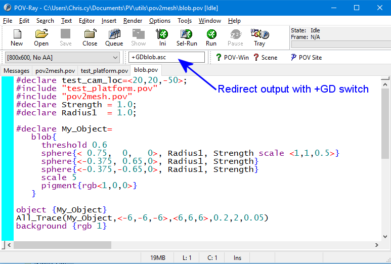
You should render this scene and redirect the debug output to a text file using the following command line switch “+GDblob.asc”. The “.asc” extension is simply an ASCII text file which we will import to a free program called Mesh Lab. Here is where you put the switch to redirect the output.

pov_gd_switch

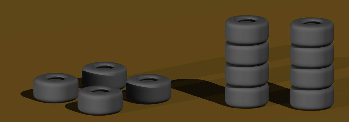
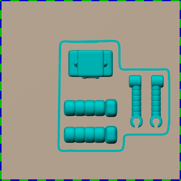
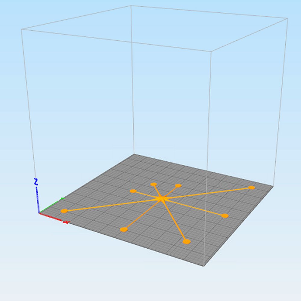
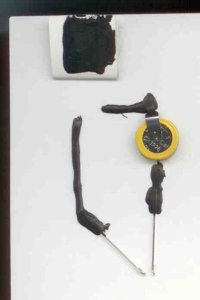
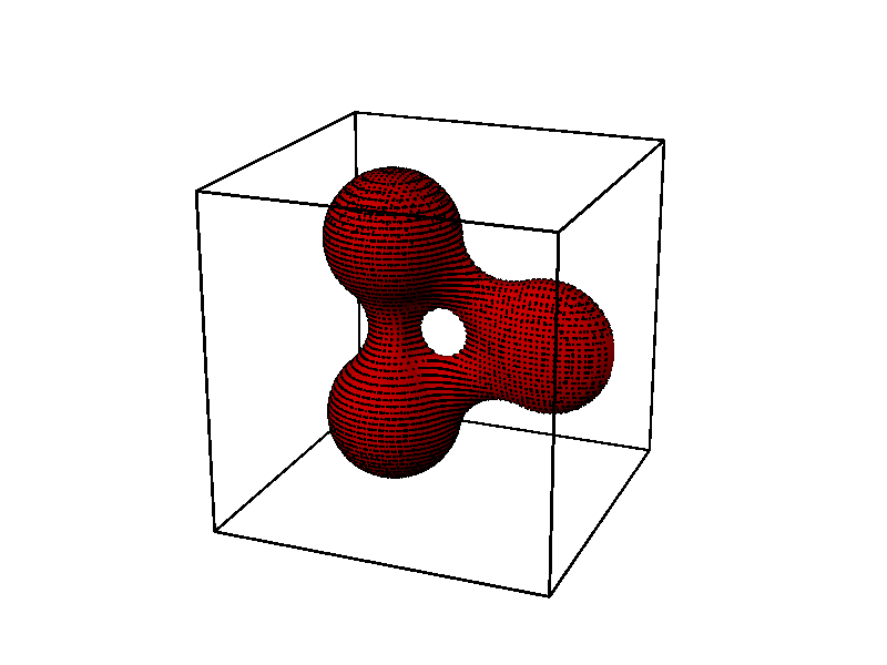
Here is the image created which shows you the dots on your object. The box around the object illustrates the minimum and maximum areas for the grid scan. We don’t really need the image that was rendered. We are only interested in the text file containing the points.

blob

This is an example of a few lines of the file we created.

-4.200000 -3.600000 -0.327045
-4.200000 -3.400000 -0.454927
-4.200000 -3.200000 -0.476401
-4.200000 -3.000000 -0.408605
-4.200000 -2.800000 -0.164190

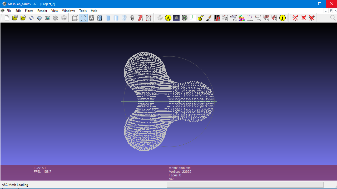
We will now import this file into Mesh Lab. It is a free program available on multiple platforms which you can download here. http://meshlab.sourceforge.net/ You can click on the images
throughout this blog to see larger versions. Open Mesh Lab and click on the File -> Import Mesh menu. A small dialog box will open and you should use the default settings. You will then see the point cloud you have imported.

meshlab_points

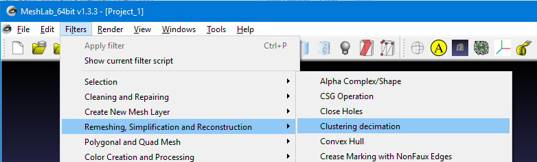
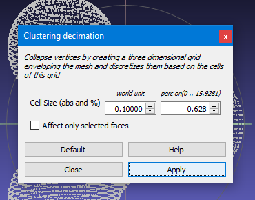
Because our scanning method could have produced identical points or points that were extremely close to one another we need to filter them out using a “Clustering Decimation” filter. You should click on the menu Filter-> Remeshing, Simplification and Reconstruction-> Clustering Decimation item. A dialog box will pop up and you should enter a number in the first field “Cell Size”. I recommend entering a world unit of 0.1 which means that any points which are closer together than 0.1 units will be combined into an average location of a single point. This value should be equal to or perhaps less than the increments you used when creating the scan of points in POV Ray. You also have an alternative percentage value that you can set if you would rather do it that way. You then click on the “apply” and “close” buttons.

meshlab_cluster_menu meshlab_cluster_dialog

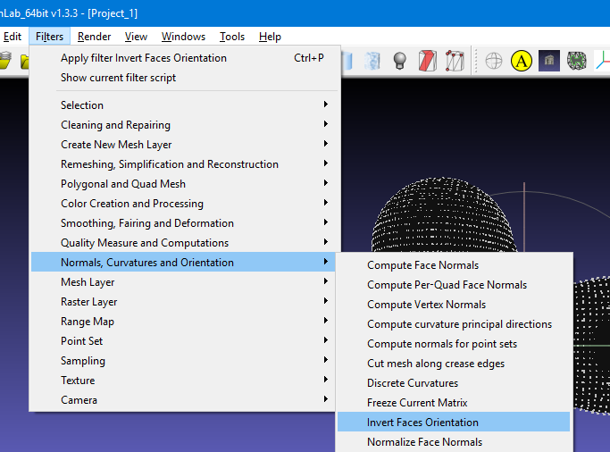
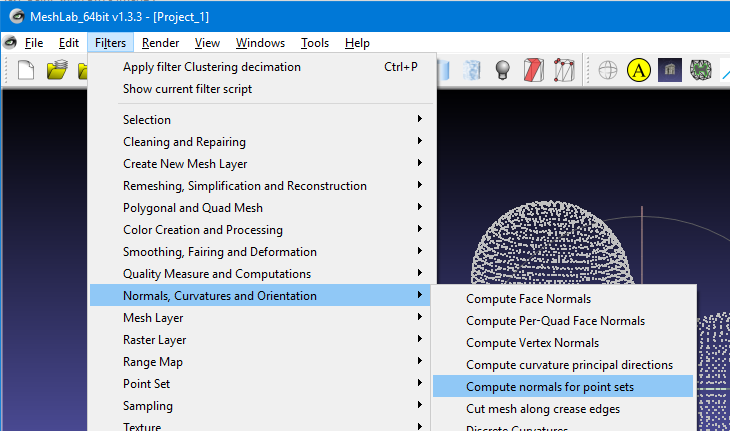
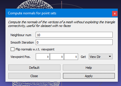
Next we need to compute the normal for each of the vertices. Although the POV Ray “trace” function gave us the normal, we have not yet figured out how to import that information into Mesh Lab. Click on the menu Filter-> Normals, Curvatures and Orientation-> Compute normals for point sets. You can use the default settings in this dialog box. Click on the “apply and “close” buttons.

meshlab_normal_menu meshlab_normal_dialog

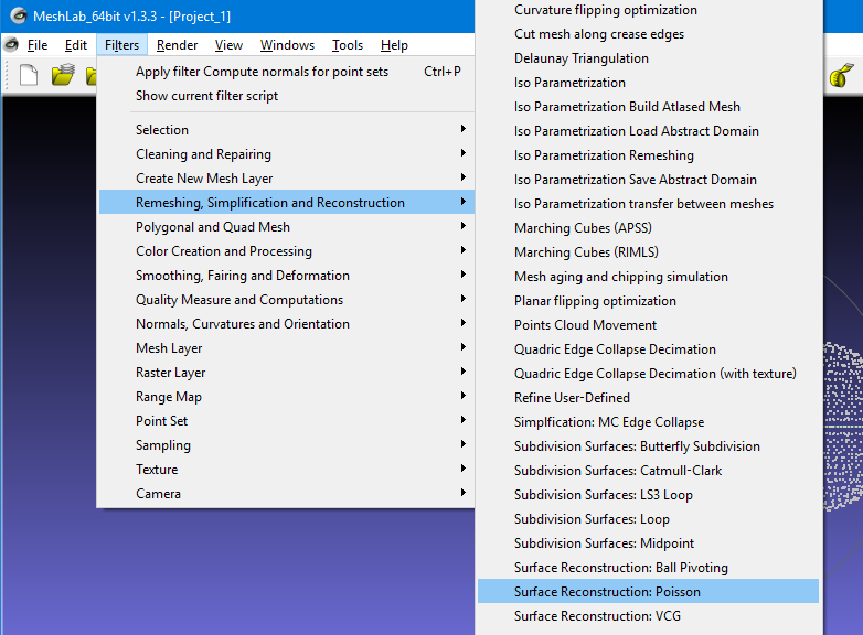
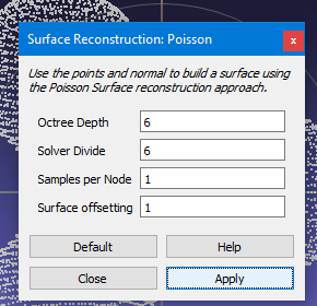
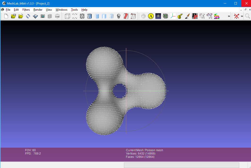
We are now ready to actually construct the faces of the mesh using the points. On the menu select Filter->Remeshing, Simplification and Reconstruction-> Surface Reconstruction Poisson. Note that there are two other methods of surface reconstruction available. The others are “Ball Pivoting” and “VCG”. To be honest I don’t understand what any of these three options mean. The Poisson method was recommended by a website I found and it works for me so I use it. You can probably use the default settings in the dialog box that pops up. Again I’m not really sure what these values do. At times I’ve tried experimenting by increasing the first two values from the 6 to 8 and the samples from 1 to 2 and at times it gave me slightly better results. Or you can just click on “apply” and “close”.

meshlab_poisson_menu meshlab_poisson_dialog

You should now see your object shaded gray like the image below.

meshlab_completed

However if it comes out very dark or black like the image below, it means that the service normals of the faces somehow got inverted and we need to force them to flip over.

meshlab_needs_flip

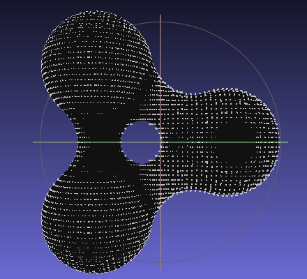
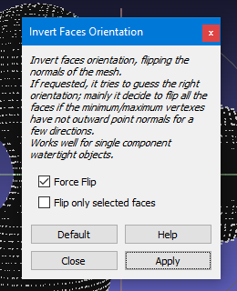
To invert the face normals use the menu Filters-> Normals, Curvatures and Orientation-> Invert Faces Orientation. Use the default values on the dialog box and make sure that “Force Flip” is checked. Click on “apply” and “close”.

meshlab_flip_menu meshlab_flip_dialogue

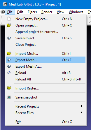
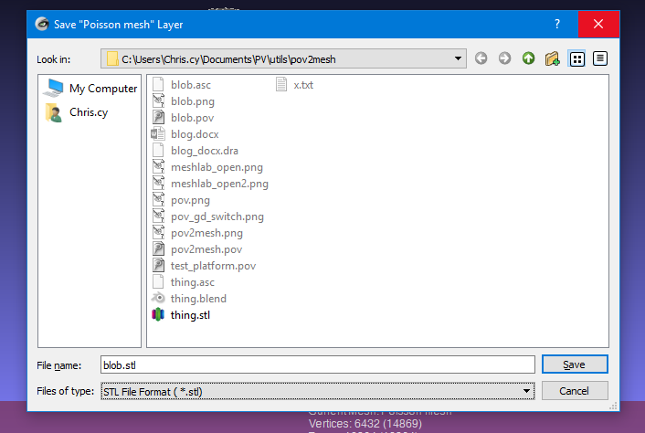
Finally we already to export our newly created mesh as an STL file. On the menu select File-> Export Mesh. Give it a filename and under the Files of type: choose STL File Format.

meshlab_export_menu meshlab_export_dialogue

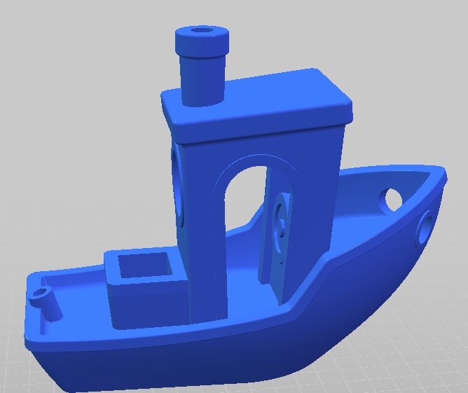
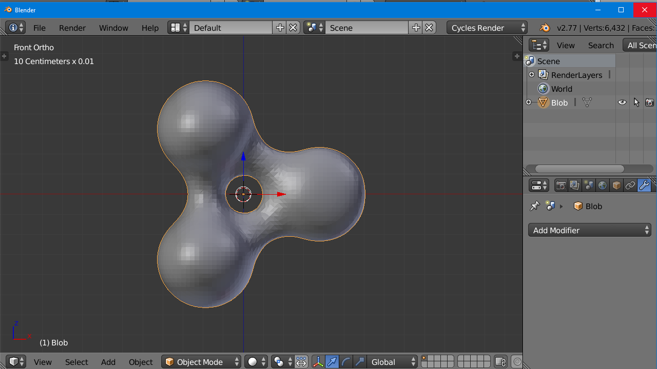
Many CAD programs and 3-D printing slicing software can import and manipulate and print STL files. We like to use Blender 3D for editing files and designing models. You can obtain it at https://www.blender.org/ We’re not going to go into any detail on how to use Blender because there are plenty of online tutorials available especially on YouTube. Also you may be using other software. In Blender balance to you can click on the menu File-> Import-> STL format. You’ll probably notice that your object is not in the orientation that you expected.

blender_imported

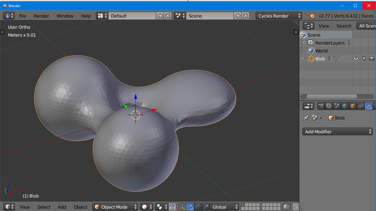
That is because the POV Ray coordinate system has the y-axis pointing upwards and the z-axis pointed into the screen. Most CAD programs have the y-axis pointing away from you and the z-axis pointing upwards. So you may have to rotate and/or mirror flip to get your object oriented properly.

blender_oriented

Here is what the object looks like in edit mode so that you can see the individual triangles. You may want to use a decimation modifier to reduce the number of triangles in relatively smooth areas while retaining detail in areas with tight radius.

blender_mish

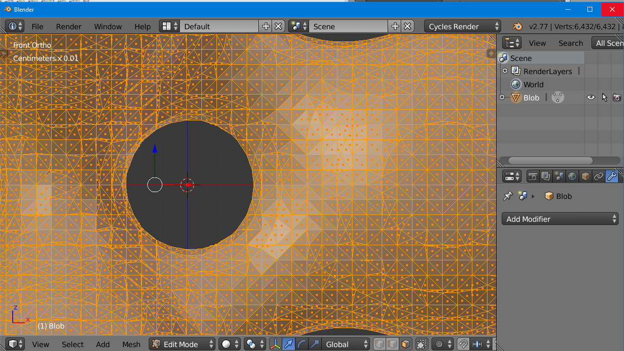
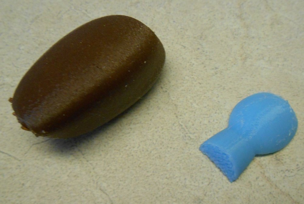
Unless you use extremely small increments, you may lose detail in converting your object. Sharp edges are never going to be completely sharp using any scanning method. You may have to do some retouching in another program. This method is really only intended for those bizarre shapes that POV Ray can render that are not available in other CAD programs.

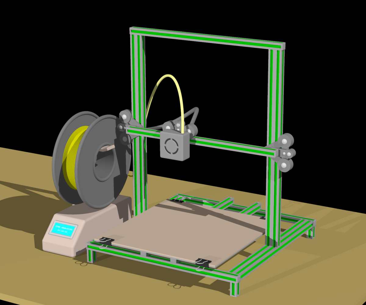
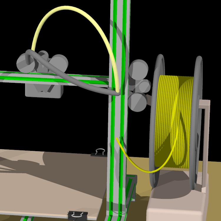
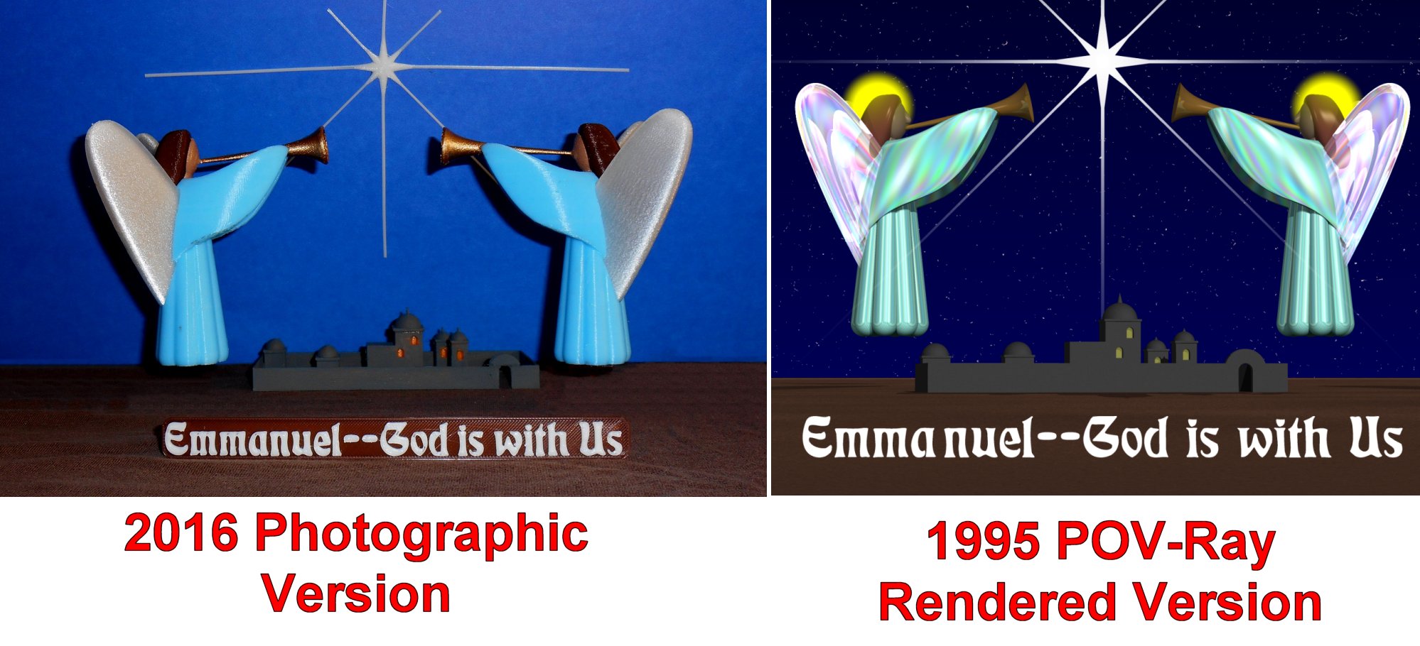
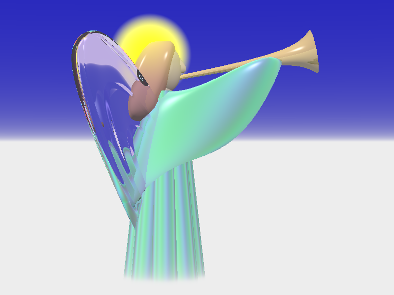
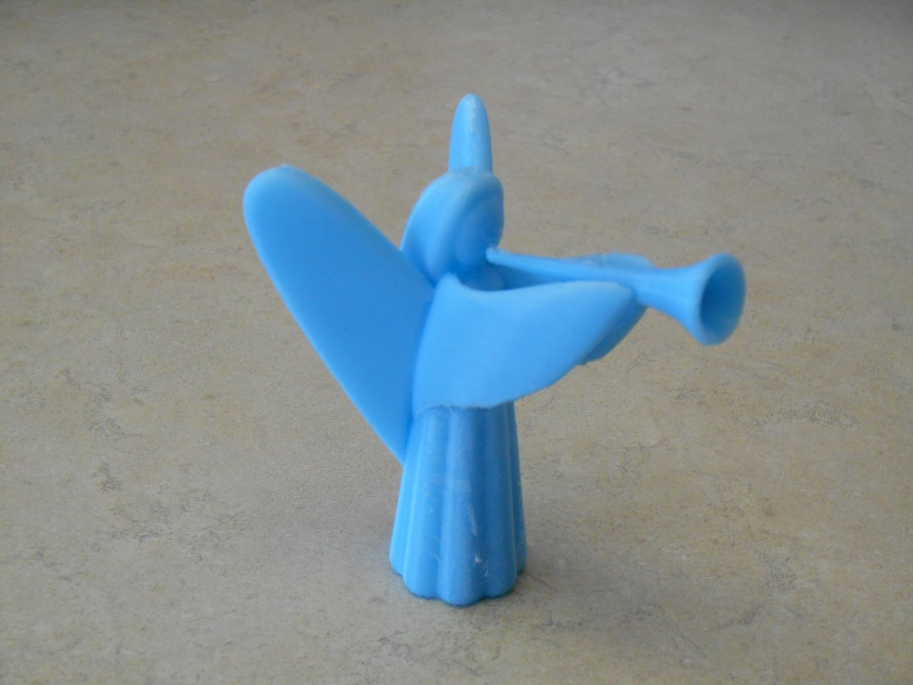
Here is a link to another article describing how I used this software to 3-D print a POV-Ray object that I created many years ago. It includes a YouTube video that shows an animated depiction of how the scanning process works.

angel1

Rendering and Animating the 2016 Rio Olympic Cauldron using POV-Ray

After watching the opening ceremonies of the 2016 Rio Summer Olympics, I became fascinated by the kinetics sculpture behind the Olympic flame cauldron. I thought about trying to make a 3-D printed version of it. However the shapes do not lend themselves to being 3-D printed on a flat bed. There would’ve been as many as 120 individual pieces to be printed and assembled. Instead I decided to just create a CGI rendering and animation. Click here to see the original cauldron from this video from NBC Sports that is used as reference material. My animated version of the object is illustrated explained is that YouTube video embedded below.

Reimagining a Classic: About This Year’s Christmas Card

This is a rather long-winded story behind the making of my 2015 computer rendered Christmas card.

I’m guessing it was 40 years ago there was a funny article in an old Mad Magazine titled “Rewriting Your Way to a PhD”. It showed a bunch of papers that a student had written starting with one in the first grade about “How I Spent My Summer Vacation”. He had visited his uncle on a pig farm and how the pigs had had funny eyes that stared at you and they stunk real bad. He then wrote a Jr-Hi book report that he somehow tied back into his experiences spending the summer on his uncle’s pig farm. It went on into a high school term paper and eventually his PhD thesis about how inner-city youth turned to crime because they never had the opportunity to visit their uncle’s pig farm on their summer vacation when they were little.

NOTE: After writing this blog, a Google search revealed this bootleg copy of the article. It was actually issue #158 from April 1973. My recollection of the PhD thesis was different but the gist of the article is as I described.

Throughout my life there have been experiences where I catch myself doing the same thing. It was a running joke with my mom with whom I shared that old story from Mad Magazine. Whenever she or I would repurpose something for a new use, one of us would say to the other “There we go rewriting our way to a PhD again”. She really loved that story.

One example of the continual rewrite is found in the creation of my computer rendered Christmas cards which I have made every year since 1995. My very first card featured a couple of angels hovering over the Town of Bethlehem with the Star shining down on the town. The figure of the Angel was based on the design of the Saint Gabriel church logo. In 1996 I reused the Angel as a Christmas ornament on a close up view of a Christmas tree with several ornaments hanging from it. Then I took the same basic design of the Angel, got rid of the wings and the trumpet, reshaped the arms, added an infant Jesus and a manger and came up with my “Mary with Child” card for 1997. Of the 20 different cards I’ve made over the years, many people told me that the 97 card was their favorite. I even did a different version of it to blow up 8 x 10 and gave them as gifts to a couple of people. I also have one hanging in my bedroom.

For reference here is a table of all 20 cards. You can click on each one to see it larger.


1995

1995

1995

1998

1999

2000

2001

2002

2003

2004

2005

2006

2007

2008

2009

2010

2011

2012

2013

2014

2015

The same basic style of somewhat abstract faceless figures has been reused in my cards many, many times. In 1998 we had the 3 Kings visiting. In 2001 I reused the 1997 scene but added Joseph to the mix. That same image was used as the cover of a CD of Christmas music created by some people at my church. The 2002 card featured shepherds and angels. In 2003 I got a little creative. I had Mary and Joseph arriving at the inn and being turned away by the innkeeper. I had to adjust the design for Mary to make her belly bulge because she had not yet delivered. You could see the empty stable in the background and the innkeeper was pointing towards it.

In 2005 which was the 10th anniversary card, I incorporated something from all of the previous cards into a nativity scene underneath the Christmas tree with presents, a piece of cake and a glass of milk for Santa. In 2009 I did an image that was really the prequel to the Christmas story. It depicted the Angel Gabriel announcing to Mary that she would be the mother of the Savior. It was loosely based on some wooden carvings from Saint Gabriel church. In 2010 I had just purchased a 3-D TV so I took the nativity scene pretty much the same as it had been in the 2005 card but I rendered it in 3-D and supplied a pair of cardboard red/blue 3-D glasses with each card. The 2011 card was clearly the most complicated design I ever made. It depicted a dining room table with a living room in the background featuring portions of previous cards and in the corner of the dining room in a china cabinet with the entire nativity scene.

Those are just the cards that reused the basic Angel or Mary figure design. The 2006 Christmas tree was reused several times. And it was based on an evergreen branch design from 1996. An image of a dove carrying an olive branch from 2004 was reused as a Christmas ornament in later cards. A Christmas stocking and a portion of a fireplace from 2007 was reused in a broader fireplace image with multiple stockings in 2008 and again in 2011. An image of reindeer from 2013 reappeared on top of my house in 2014. I could go on and on about the various pieces of one card that reappeared in later cards.

Despite the fact that I have been “Rewriting My Way to a PhD” every year for the past 20 years, I have always considered each new card a new design which simply incorporated elements from previous cards. Of course the challenge each year was to come up with something new and better. Sometimes I sort of copped out by doing something really simple like the fractal Christmas tree design from 2000 or the very simplistic dove from 2004. But most years I attempted to outdo myself each time.

Well fans… unfortunately the well has run completely dry. I am officially totally without a new idea. Last year’s card featured Olaf the snowman from the movie “Frozen” sitting in my front yard. Since I bought a 3-D printer for my birthday this year I thought about doing the same image of the front of my house with a giant 3-D printer turning raw snow into multiple snowmen. But most people don’t know what a 3-D printer looks like and it was just too much of an inside joke. I was afraid nobody would get it. I could’ve put a big sign on it saying “Snowman Printing 3-D Printer” but any joke you have to explain just isn’t worth it.
I started “leaking” the news to various friends and family that this year’s Christmas card was likely going to be a completely reissued copy of a previous card. The classic 1997 Mary with Child seem to be everybody’s favorite and I had hoped that bringing back a favorite would minimize any disappointment that there wasn’t something new and better. I told people I was considering touching it up a little bit. My sister Carol asked “Was there something that you wanted to do in 1997 that you couldn’t do because the computer wasn’t powerful enough? Technology has come a long way and you are making way more complex designs than you used to?” Indeed the software and hardware had significantly improved. There is no way I could’ve done some of the later cards using 1997 technology. But there really wasn’t that much that I could upgrade in the image from 97. Here’s a closer look at the card.

mary97

There was one part of that card that I didn’t particularly like. I was never completely satisfied with the stone wall in the background. I had used a technique where you basically create an image of the wall separately from the main image and then render it as a flat background behind your figures. Looking at it for the past 18 years I’ve often thought it looked just too fake. If I could change anything about that image I would’ve redone the wall. I didn’t want to spend too much time on this. It wasn’t just that I was out of ideas that brought me to this place. I also had so many other things going on that I didn’t have time to create something new from scratch. When I’m designing these cards have to put aside the whole day for several days where I can bury my head in the work and do nothing else. I just didn’t have the time to devote to it this year.

When Hollywood remakes a new movie that is basically a retread of an older film, they’ve stopped calling it a remake because that’s just too cheesy. Somewhere along the way they came up with the phrase “a reimagined version of the original”. So that’s what I was going to do. I was going to reimagine the 1997 card and I would start with that ugly stone wall.

Before I “reimagined” the stone wall, I realize I had already done some reimagining of the Mary figure. The computer model of the figure from 1997 was supposed to be just a one-time thing. But as I kept using the same basic design for other figures over the years I wanted to come up with a standardized body and a standardized way of manipulating the arms and the head when I attached them. I had forgotten that I had made some changes to the Mary figure after 97. When I put the original Mary into a scene such as the 3 Kings, she looked a little bit out of proportion. She was a little too short and too wide. I also modified her to be in a kneeling position for the 3 Kings image and as I did so, I completely redesigned the figure.

My rendering program POV-Ray has evolved over the years and I couldn’t even get 1997 code to render properly with the latest version of the program. So I tried to take the updated model and put it into my reimagined 1997 scene. It just didn’t look right. One of the dramatic parts of that original was the way her arms so fully envelop the infant. I never realized it but to get the right impact for that particular image, she needed to be out of proportion. There was one other difference I hadn’t noticed. I was used to looking at the 8 x 10 version of the image that has been hanging on my wall for years. But the original Christmas card was much taller and narrower.

mary8by10 mary97

In order to get it to look right for the wider 8 x 10 framed version, I had actually cheated. I just arbitrarily moved the Mary figure down a little bit to get it to fit in the frame properly. You couldn’t tell it because the floor was chopped off but if you look at a wider version of the 8 x 10 image here, the bottom edge of her robe is actually embedded in the floor.

no_feet

By lowering her to get it to fit the frame, it even added to the slightly disproportionate aspect of the image. But it was that disproportion version that I and my friends have been working for years and I wanted to get that back again. Rather than trying to get the updated model to look like the old one, it was easier to fix the old model so that it would render properly with the updated software. Basically I spent a day and a half trying to fix this and when I was done all I really had was my original image back again. It wasn’t until the second day that I actually got around to fixing the thing I wanted to fix… the wall.

An early version of that wall used a mathematical pattern known as a Voroni diagram. You take a random set of points in a flat plane and computes a series of irregular shaped polygons such that every point within the polygon is closer to its central point than to any of the other surrounding random points. The POV-Ray rendering program has a built-in Voroni which created shapes that were nicely random but they varied in size too much. It would end up looking like there were some very tiny bricks and some very huge bricks. Instead I spent a lot of time back in 97 coming up with my own design which simply started out with a hexagonal grid like a honeycomb. Then I randomly moved the corners a short distance to make the bricks look irregular. It’s not obvious that each of the bricks actually started out having six equal sides. It was better than the totally random Voroni version but I still didn’t like it. It was the best I could do at the time.

The 2009 card which featured the Annunciation included a new brick wall that I designed for the card. It consisted of long rectangular slabs of sandstone and was modeled after the exterior sandstone brick on Saint Gabriel church. I had tried to come up with a mathematical formula to randomly size slabs and assemble them into a wall but in the end I sort of did it manually picking the size and location of each individual block. If I had had to do that for the tall wall in this new image it would take a long time. Even if I had found a way to automatically lay the bricks, I wasn’t sure that this type of stone was appropriate for a stable behind an inn in biblical Bethlehem. It looks too modern.

It just so happens that I’ve been watching a lot of TV shows set in medieval times with lots of stone castles. Shows such as “The Last Kingdom” and “The Bastard Executioner” have some really nice castles. The patterns I saw were rectangular blocks that were to be about 6×10 inches laid in a uniform height row with a typical 50 percent overlap like a modern brick wall. They look a little bit like concrete blocks using construction today. However they were smaller and they were very rough cut without sharp edges like you would see on modern bricks or concrete blocks. While they seemed to be of roughly uniform height, there was some randomness to their length. I tried to introduce that randomness but then the 50 percent overlap would get out of phase further down the row and the bricks would no longer interlock. They would have long vertical seams of mortar. I finally came up with a formula that would adjust each brick length by a random amount and then readjust the next one back by the same random amount. Then the next one would be randomly fudged repeatedly. That way the overlap didn’t get too far out of phase.

Although I wasn’t able to re-create something that looked exactly like what was used in these TV shows, after a day or two of tinkering I did come up with a stone pattern that I liked. Here is what it looked like.

blank_wall2015

I could have quit right there but I noticed that there was a lot of empty space in the image. As I’ve mentioned a couple of times, I’m accustomed to looking at the 8 x 10 version and the objects in that version fill the frame more fully. The version from the card would be taller and we would not have Mary’s feet sticking through right for the floor. That left a lot of empty space. There just wasn’t enough going on considering the complexity of the images I’ve been making in recent years. Although I liked the new wall, there was too much of it. I should also note that even though this 2015 version was going to be tall and skinny, it was a slightly different shape than the 1997 original. Back then I was printing the cards myself on glossy card stock that was 8.5” x 11” folded in half. Also my printer would not print all the way to the end of the paper. The final image was printed 7.75” x 4.75”. However in recent years I’ve been getting the cards printed at VistaPrint.com. They claim that their cards are 5” x 7” but they actually trim them down from that size and you have to render them slightly larger than that size so that it prints beyond the edge. You have to give them something extra to trim off. The bottom line is I’m rendering these cards at 7.2833” x 4.7233”. In other words it’s 2185 x 1417 pixels which is a totally weird size.

In order to deal with the fact that there was too much wall, I came up with the idea of cutting the wall down to only go up halfway. Then I could put the Star of Bethlehem shining through and some other Bethlehem buildings in the background along with a starry night sky. The Bethlehem buildings have been around since the very first card in 1995 when they were rendered extremely small in the distance. But the 3 Kings version in 98 had been blown up bigger with the star in the background. By the way the star from 98 and this image were created much differently than they were in 95. The 1995 star was actually a physical object model. It was made out of cones and long thin cylinders to simulate the rays radiating from the center. The 1998 and current star were created by a piece of software called a “lens flare simulator” that had been around since 1998. Basically you tell it where the light source is, where your camera is, and then it puts up a transparent flat plane in front of your virtual camera and draws the star pattern on it with the lens flare rays radiating from it. It’s sort of like putting a piece of glass in front of your scene and drawing the star on the glass.

If I had felt like spending more time on the image, I would’ve redesigned the Bethlehem buildings. They were originally meant to be rendered very small in the distance so they don’t have any detail to them all. With them blown up this big, I probably should have updated them a little bit perhaps putting shutters on the windows or adding other details. This is what the image looked like at this point.

no_sheep

After putting all that work into the stone wall, it still felt like there was too much of it. If this was a stable, we needed animals. I’ve always wanted to do a cow or perhaps the donkey that Mary rode in on. But I wasn’t going to take on the job of creating a new animal from scratch when I was trying to get through this one as quickly as possible. I had sheep from previous cards. So I threw in a sheep.

With the wall only going halfway up, it made it look like they were outdoors standing in front of a wall rather than in a stable. So I put up some wooden beams which dated back to the 3 Kings image from 1998. Here is the final image.

final2015

Here is the 1995 image side-by-side with the 2015 version. Although I added a lot more to the image then hired to dissipated I would, I still think it’s a redo or reimagined version of the original and not a totally new image. But I like it and I hope you do too. Here are the two images side-by-side.

side_by_side

Because the new cards are a different shape, adding the wooden beam to the left does help fill up some space in the sheep, star, and buildings and a nice touch as well. Ironically after putting all that in, you can see very little of the new wall.

The final task was to compose something for the inside. I used to put the descriptions on the back cover and use the two inside pages for Scripture quotes. On the left panel I had put

“Therefore the Lord himself will give you this sign: the virgin shall be with child, and bear a son, and he shall be called Emmanuel – Isaiah 7:14”

On the right panel I had put

“For unto you is born this day in the city of David a Savior, which is Christ the Lord. And this will be a sign for you: you will find an infant wrapped in swaddling clothes and lying in a manger”. And suddenly there was a multitude of the heavenly host with the angel, praising God and saying: “Glory to God in the highest and on earth peace to those on whom his favor rests.” – Luke 2:11-14

That particular quote was pertinent because it describes the manger and the swaddling clothes. I could have stopped at the manger because there were no angels in this image. This quote was more fitting to my 2002 card with the shepherds of the Angels because that is where this quote comes from. However the entire quote is what Linus read at the end of “A Charlie Brown Christmas”. Because of that connection I wanted to keep the entire quote. It is different because he was reading from the King James version but this is New American Standard translation.

Since I started having cards professionally printed, I use the inside left panel to describe the card and the process that I use. That only leaves the right panel so I dropped the Isaiah quote and stuck with the Luke scripture. I thought it was especially fitting since this is the 50th anniversary of “A Charlie Brown Christmas”.

To tie into that quote I originally had added my own message “May the peace of God’s favor rest on you this new year and always!” Looking at it in 2015 I realized it didn’t say Merry Christmas which of course these days is a mortal sin. You can have a Christmas card with the Virgin Mary, the infant Jesus, the Star of Bethlehem and Bethlehem itself (not to mention the sheep and a stable) but if you don’t say Merry freaking Christmas somebody was going to complain 🙂
So this year I rewrote it to say “May the peace of God’s favor rest on you this Christmas and throughout the new year!” It still doesn’t say “Merry” but these days I would wish more peace upon people and I think the merriment would take care of itself. I dropped the word “always” because I signed the cards for friends and family “Love always, Chris”. More distant acquaintances get a just plain “Chris”. Who knows I may not love them always. We will take it year by year on the rest of them 🙂

On the inside left panel I wrote a much briefer version of how and why the card was reimagined for this year. Among the things I noted was that the card has nearly 5 times as many objects in it and was rendered at a higher resolution (more pixels) but took way lesst time to complete. In the box below is the text that appears inside the card. But for now I’m wrapping up this blog entry and wishing you all a very Merry Christmas, peaceful and blessed New Year, may the force be with you, happy holidays, happy Hanukkah (or however it’s spelled) or just plain party on dude!

About This Card

In 1995 I began designing, computer modeling, and rendering Christmas cards to send to friends and family. Each year I came up with a new design. I usually reused some of the models from previous years but the design itself was always something new. Unfortunately after 20 years the well has run dry. This year I was completely out of ideas for a new card. I originally planned just to re-send my old 1997 card which is a favorite. Then several people suggested that I take an old card update it. So I did. The image of Mary, The Child, and the manger appear exactly as they did in 1997. I never liked plain stone wall behind them but it was the best I could do with 1997 technology. So I redesigned the wall this year. It is the only new element in this design. It still looked bland going all the way to the top so I only put it halfway. I then added the Star and wooden beams from my 1998 card, the background buildings from 1995, and sheep from 2002. The Scripture is the same one I used in 97. Linus quoted it in “A Charlie Brown Christmas” 50 years ago this year.

The Mary figure is made of fourth order quadric mathematical surfaces. The swaddling clothes are hyper complex julia fractal surfaces. The original design took me 5 days to design and I put 2 more days into this year’s update. The original image was rendered using POV-Ray 3.02 at 1150×700 pixels on a 200MHz Pentium Windows 95 PC. The original model had 6000 objects and took 16 hours to render. The new version contains over 29,000 objects and took just 71 minutes at 2185×1417 pixels on an Intel core i7 under Windows 10. Time sure have changed 🙂 Rendering was done using POV-Ray 3.61 software which I helped write. Visit my blog to learn more about my cards.

email: cy_borg5@cyborg5.com
blog http://graphics.cyborg5.com/
http://www.facebook.com/cyborg5
http//www.povray.org:
© 2015 Chris Young, All rights reserved.

Fairgrounds Coliseum Panorama January 2, 2015

Here is a panoramic picture stitched together out of six individual photographs taken by my sister Carol while we attended the hockey game at the Indiana Fairgrounds Coliseum on her birthday January 2, 2015. Click on the image to see it full-size.
Hockey_01_02_2015_small
Also here is a video we shot a really cool radio controlled blimp they have at the Coliseum. Also shows the panorama

Do you want to build a snowman? My 2014 Christmas Card

Each year I create a computer rendered Christmas card using the Persistence of Vision Ray Tracer POV-Ray. I often try to have the card reflect some things that have been going on in my life. For example in 2010 we got my first 3-D TV so I created a 3-D Christmas card. I included red/blue glasses with each one. Last year after working a lot with electronics I decided to put a blinking red LED on Rudolph’s nose as I outlined in my previous blog entry here.

One of the big events of 2014 was we had a break in at my house so the house was on my mind a lot. We lost that 46 inch 3-D HDTV that I just mentioned and my dad lost a couple of expensive wrist watches but other than that the only thing we lost was peace of mind. We gained a replacement TV and a new alarm system.

In other news… I’m a big fan of the TV show “Once upon a Time“. When I heard that they were going to do half the season based on the Disney film “Frozen“. I’m a huge fan of computer-animated films from Pixar, Disney, DreamWorks etc. however I have not seen “Frozen” because it just didn’t look that interesting. But with the new season of “Once upon a Time” based on the film, I took the time to watch it and became completely obsessed which is really embarrassing since I’m not a six-year-old kid, I’m a 59-year-old man.

While most of the kids who enjoy the film get obsessed with the song “Let It Go”, I couldn’t let go of “Do You Want to Build a Snowman?”. ABC ran a special about the making of “Frozen” and I was shocked to learn that “…Snowman” was almost cut from the movie! I’ve become so obsessed with the song that I’ve even taken to writing parodies of it such as this one.

Having already created Christmas trees (2006), reindeer (2013), and a little Santa Claus figure (2011) and a variety of interior Christmas scenes, it was time to put it all together in an outdoor Christmas scene featuring my house. Except for the main Christmas tree, the reindeer, and the Santa figure everything in this scene was newly created for this card such as the bushes, the small tree in my office window, Santa’s sleigh, and of course the entire house. The biggest challenge was to try to come up with a formula for isosurface objects that would realistically look like snow. The snow texture itself was tricky trying to get random sparkles.

One item of note is a little blue sign sitting in the yard just left of the snowman. That’s a sign for the Guardian Alarm Company.

Here is the final image. You can click on the images to enlarge.

card14

These two images show what the interior of the card looks like.

insidea
insideb

At some point I will do a more detailed description of how I created this and other cards.

Here is a link to a Facebook album showing all my previous cards.

Shining Your Light on Christmas: Making a Ray-Traced Christmas Card

Each year it’s a challenge to come up with a new design for my famous ray-traced computer-generated Christmas cards. Sometimes when I run out of ways to outdo myself from a previous years card I come up with a gimmick. For example in 2010 when I had just purchased a new 3-D TV I decided to make a 3-D Christmas card. I rearrange the figurines in an older card that showed a nativity scene and rendered it in 3-D. Each card came with it on set of red/blue anaglyph 3-D glasses for viewing. I also made an animated version where the camera moves in and around the scene. It was a little video clip that I could show on the 3-D TV. Click here for a YouTube version.

This year I was totally stumped on what to do next. I’ve done almost all of the religious themed cards that I could think of. I’ve done Mary and the Child (1997). The Three Kings (1998). Shepherds and Angels (2002). Mary and Joseph and Child (2001). Mary and Joseph and the Innkeeper (2003). I’ve done various Christmas trees some close-up with just a few ornaments (1996). An entire decorated Christmas tree (2006). Then I did a Christmas stocking (2007), a fireplace with multiple stockings (2008). In 2011 I had my most complex card ever been included a Christmas tree, fireplace and stockings, a dining room table with Christmas decorations including a china cabinet in the background full of plates with various patterns on them. Last year I did a close-up of the same table Christmas ornaments hanging in a cone shape that resembled a tree. There just isn’t much else to do.  Here is a link to a Facebook album showing all of my computer-generated Christmas cards.

The only area of Christmas that I haven’t explored is more of a kid’s theme with Santa Claus, reindeer, snowman etc. So I decided that was the road I needed to explore next. However except for a small Santa figure on the dining room table scene, I had not created any objects from this genre. One of the things that makes these cards easier to make your after year is that I can reuse models and reincorporate them year-to-year.

Perhaps it was time for another one of my gimmick cards that reflects what’s going on in my life currently. If I look back over the past year the thing that is occupied my life most is taking up the hobby of electronics. I built multiple gadgets using Arduino-based microcontrollers and I have the little credit card sized computer known as the Raspberry Pi which I’ve been playing with.

pen

There is a company called Bare Conductive that makes electrically conductive ink and paint. They sell little kits where you can make greeting cards that have blinking LEDs and tiny button sized batteries. You connect the LEDs to the batteries using their special electrically conductive paint. They have a card that shows Rudolph the Red Nosed Reindeer with a blinking red nose but it is a horribly stylized design that I thought was really unattractive. In addition to selling kits for single cards, they will also sell you a package of 50 LEDs and 50 batteries along with a paint pen for drawing the lines. So I ordered a tube of paint and the LEDs and batteries and started work on my own version of Rudolph.

battery led50

I needed some reference images to design my reindeer. I decided I wanted him to look like the stop motion animated figures from the 1964 Rankin/Bass produced TV special which is still erring even this year. I got a copy of the TV special and did some screen grabs. In the early part of the show Rudolph is very young and has not yet grown antlers. Halfway through he grows up into sort of a teenaged reindeer. He has a good set of antlers but they are not as full as some of the other reindeer. Here are some of the reference images that I used in designing my model.

Screen grab images from Rudolph TV special use as reference images.

Screen grab images from Rudolph TV special use as reference images.

I wanted more than just Rudolph although I could have put him on the ground in the snow perhaps with Santa and some elves standing around. However one of the nice things about creating these computer models is it’s easy to duplicate them. Once you’ve got one reindeer it’s a snap to make eight or nine. I had so much difficulty modeling the antlers the way I wanted them that I didn’t feel like making a different set of more mature antlers for the other reindeer. (You can click this image  for a larger version  as well as other images  in this blog.

Test rendering of Rudolph

Test rendering of Rudolph

One problem was that the LED is relatively big when you think about sticking it on the nose of a reindeer. If I filled the scene up with too many other things, Rudolph would be too small and his nose would be gigantic. So I had to make the Rudolph character be the primary ature in the scene. I did some test renderings with eight reindeer and Rudolph in the front row. It turned out I really didn’t have room to create a sleigh with Santa and a bunch of toys. So it turns out that the sleigh is sort of off the edge of the screen not visible just implied.

8deer1

Then I had to figure out what to do for a background. I could have just done a plain white background and had them sort of abstract. But I really wanted to create a full scene. It would be easy to create a night sky perhaps with stars or snowflakes but I wanted to give it some perspective so I needed a ground scene. It would’ve taken me weeks to come up with a bunch of tiny houses or buildings covered in snow on the ground extending to some horizon. My friend Rick Ruiz suggested maybe a photo background. I started doing Google image searches for nighttime Indianapolis skyline. I needed something that was recognizably Indianapolis but have lots of sky. I finally found the following image.

night1

Unbeknownst to me, this image was a copyrighted photograph by photographer Rich Bell. I do not recall where I obtained the image but it did not contain any visible copyright notice. I did not bother to check the metadata and after resizing and manipulating the image the metadata was lost. In 2016 my use of the image was the subject of a copyright infringement lawsuit brought against me by Mr. Bell. We eventually settled the dispute and of court for undisclosed terms. The image shown here is a legitimate licensed version of the image. Although I believed that my use of the image constituted “fair use” under copyright law, it would’ve cost me thousands of dollars of legal fees and over 18 months in federal court to see the case through to its ultimate conclusion. There is a public perception that anything on the Internet is fair game but it most certainly is not. Any content creator wishes to aggressively pursue their rights under the law may do so. Let my story serve as a cautionary tale. I will have more to say on the topic in a separate blog post at some point.

I had to extend the sky higher and clip off the bottom of the image that shows the city lights reflected in the canal. Now that I had decided that the reindeer would be in flight over the city rather than standing on the ground I had to remodel their legs to put them into more of a swept back flying position. Also my original design had been flying from left to right but the way the buildings were arranged in the skyline I had to flip the reindeer around so they were flying right to left.

bg2

I still have the problem that the legs of the reindeer were partially blocking the skyline. I had to keep moving the skyline image lower in the scene, adding more black space at the top. One of the problems was that the shorter buildings such as the state capital were disappearing off the bottom of the card. So I took some creative license and did a cut and paste to move the capital dome and some of the other buildings on the lower right up higher in the image. It doesn’t mess up the perspective too bad.

bg3

Here is the final image.

final13

I sent the image off to VistaPrint.com to have them printed and soon the parts arrived from Bare Conductive to add the LEDs. We experimented by connecting an LED to one of the tiny button batteries and we let it sit to see how long it would run. After about three days it was still going but it was very very dim.

I generally try to put some sort of Scripture quote on the inside of the card along with a Christmas greeting. I came up with the theme of letting your light shine on Christmas and immediately thought of The Sermon on the Mount where Jesus says to the believers “You are the light of the world… Let your light shine…” So here’s what it looks like on the inside of the card.

greeting

The examples they show on the Bare website show you how to use a little flap of paper to make a switch. You leave a gap in the circuit and then coat the flap with the conductive paint. As you hold close the flap it completes the circuit and the LED lights up. The nice thing about these LEDs is that they don’t require any other circuitry or resistors. They just blink on their own. Here are some images of my circuit.

Paper Flap Switch Open

Paper Flap Switch Open

Paper Flap Switch Closed

Paper Flap Switch Closed

One of the big problems all along in this project was deciding how I was going to mail them. Almost half of them would got people that I see on a regular basis and so I could just hand-deliver them. But many of them are out of town or are people who I don’t see very often in town and would need to mail them. I asked a photographer friend if he knew where I could get boxes that were the size of a 4 x 6 photo since that was the size of the greeting cards. He told me that everything is digital these days and photographers mostly just give the client a Photo CD other images and perhaps a few big prints. One company that made boxes for photos had gone out of business.

DVD mailer from Staples

DVD mailer from Staples


After doing some Google searches I realize that boxes made for mailing DVDs would be just about right. I’m not talking about flat envelopes were padded envelopes. These were boxes for mailing a boxed DVD. The post office has some that are just the right size and you can get them for free but you have to mail them using priority mail. That was likely to be more expensive. I finally found almost the same thing at Staples.com at a reasonable price and so I ordered them. Later that same day I got a phone call saying that they were out of stock and I could reorder in a few days. They did not offer to put them on backorder for me.

uspsI went ahead and ordered the priority mail boxes from the post office. Then I started figuring out the price. If I could go regular first-class I could mail a 2 ounce box for a little over two dollars. But if I was going to mail priority mail it was going to cost me five dollars each! I suppose I could have taped over the “Priority Mail” logos all over the boxes and disguised them but that was probably a federal offense.

I tried looking at Office Depot and Office Max and they had something similar but they would only sell them in packages of 50 and they cost $30-$33. Out of the 30 or so LED cards I was making, I had narrowed it down to only 13 or 14 bit to be mailed. By the time I had paid a high price for 50 boxes, the cost per card was back up to the point where it was similar to the free boxes and the priority mail postage costs. I tried reordering at Staples a few days later we got the website said “in stock”. Unfortunately two days later I got an email saying “sorry they are out of stock”. So we are going ahead with the priority mail postage.

I generally send about 65 or 70 Christmas cards each year. Because I was worried that we were going to ruin some, I went ahead and ordered 100 cards even though I could’ve ordered 75. It was a good thing because we did run a couple of cards and I always come up with some people I want to send to at the last minute.

Because dad was going to be the one to have to assemble all these LEDs and batteries and little paper flap switches and because I didn’t want the costs to get too big, I picked out about 30 people who are family and my closest friends to get the special edition. The other 30 people will get a plain Rudolph Christmas card without the LED. (Shhhh… don’t tell them).

We also ruined a couple of cards because after we had them assembled we discovered that my package of 50 red LEDs actually contained five or six green LEDs! When these LEDs are not illuminated they look completely clear so you can’t tell what kind they are. Somebody messed up at the factory. They are going to get an email from me.

Here is a video of what the card looks like with Rudolph’s nose blinking.

Many thanks to my dad who assembled all of these cards, assembled the boxes for mailing, stuck on the mailing labels, and hauled that all off to the post office.

satb100I had to show off my card so I couple weeks ago I participated in the weekly Adafruit Show-and-Tell video chat on Google plus. Here is a link to that video in which I also showed off some computer-controlled Christmas lights. My segment of this 22 minute video started about the four-minute mark. But the other projects shown that night were really cool as well.

Now what the hell am I going to do next year??? I guess I will have to add sleigh, Santa, and some toys and skip the LEDs.